|
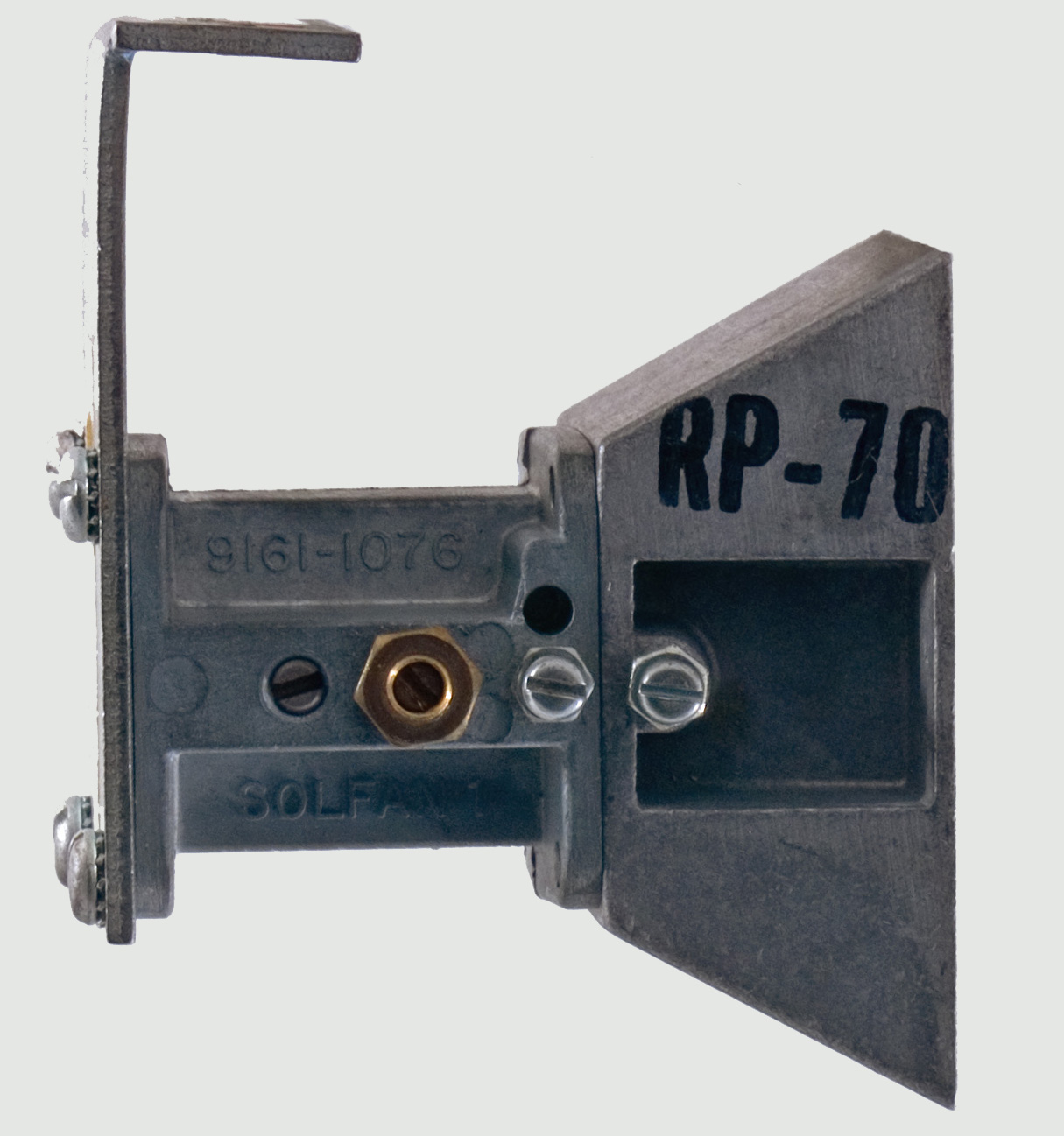
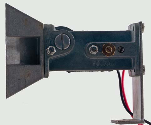
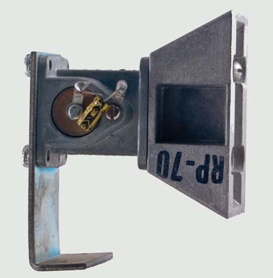
The in-line Solfan module complete with fixing bracket and 6 dB horn.
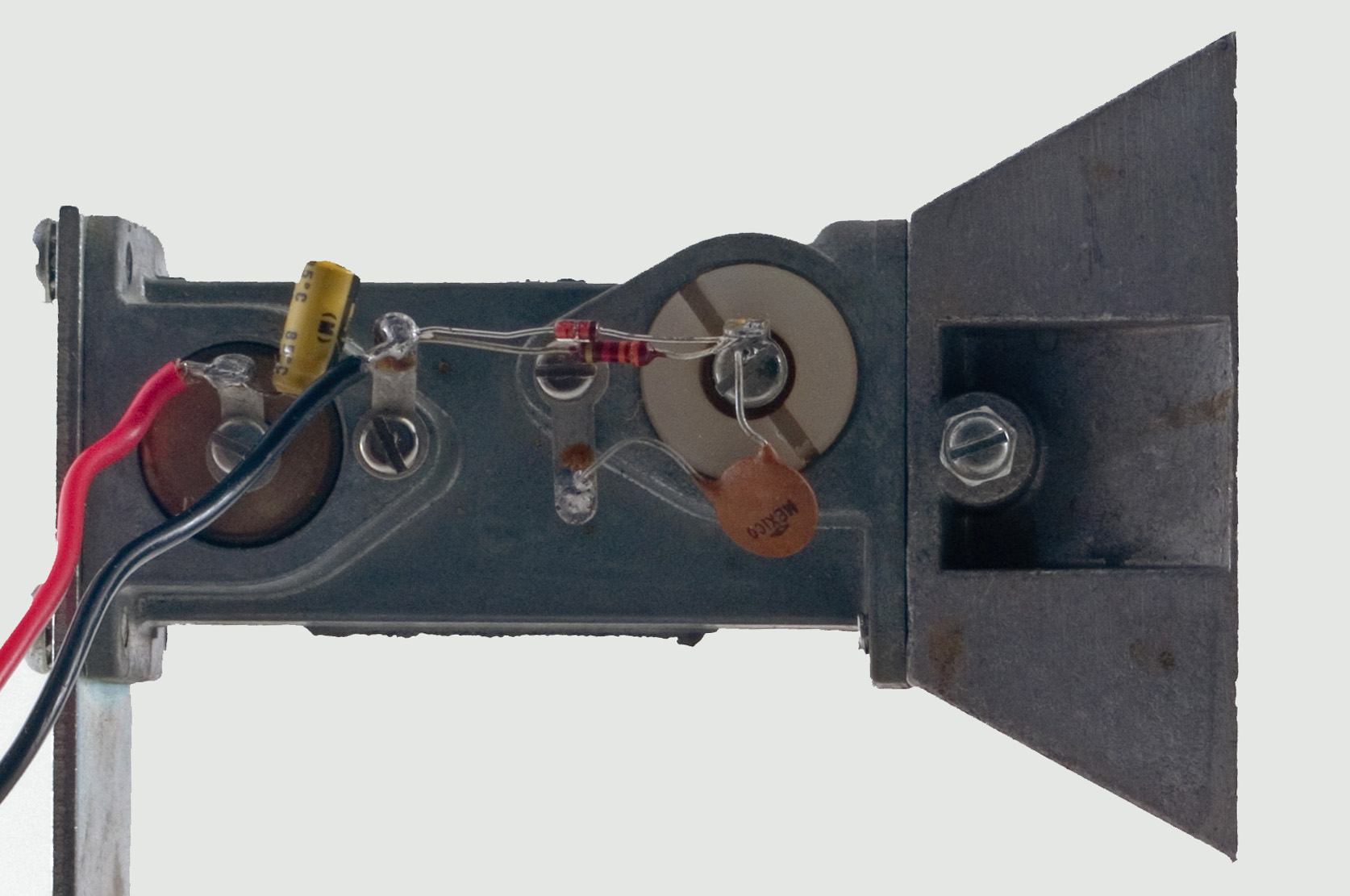
The American made Solfan intruder alarms featured gunn oscillators in a heavy die-cast housing and were very popular on the surplus market in the 1980s. The most useful of the modules was the in-line mixer version as shown above. The nominal frequency of 10.6 GHz was easily adjusted downwards to the amateur band by moving the main brass screw inwards to make a fixed frequency source.
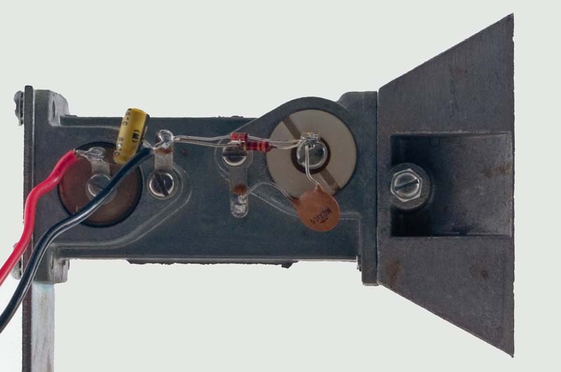
To make the module mechanically tuneable a small modification is made. In the picture the gunn return (black) lead is made to the post adjacent to the Gunn device. This screw is removed and the hole is drilled and tapped to 2 BA. This operation is done with the back bracket removed so that all pieces of swarf can be cleaned out after drilling. A 2 BA threaded PTFE screw is then used as the frequency adjustment.
The frequency setting was typical of adjustments made to any of these Doppler modules. The PTFE tuning screw would first be inserted through the casting until the end was flush with the cavity wall. The brass course adjustment was then moved so the the oscillator was set to the highest frequency required in operation. With this accomplished the tuning range achieved by altering the cavity insertion of the PTFE thread was of the order of 300 MHz. The tuning was at its slowest rate when the thread was close to the cavity wall and the rate of frequency change per turn increased with the depth of penetration.
From left to right in the main picture can be seen the centrally mounted Gunn device, earth posts and the off centre mixer diode mounting. The diode de-coupling capacitor disc makes the use of a 100 MHz difficult as the signal is by-bassed to earth. An IF of up to 35 MHz worked well.
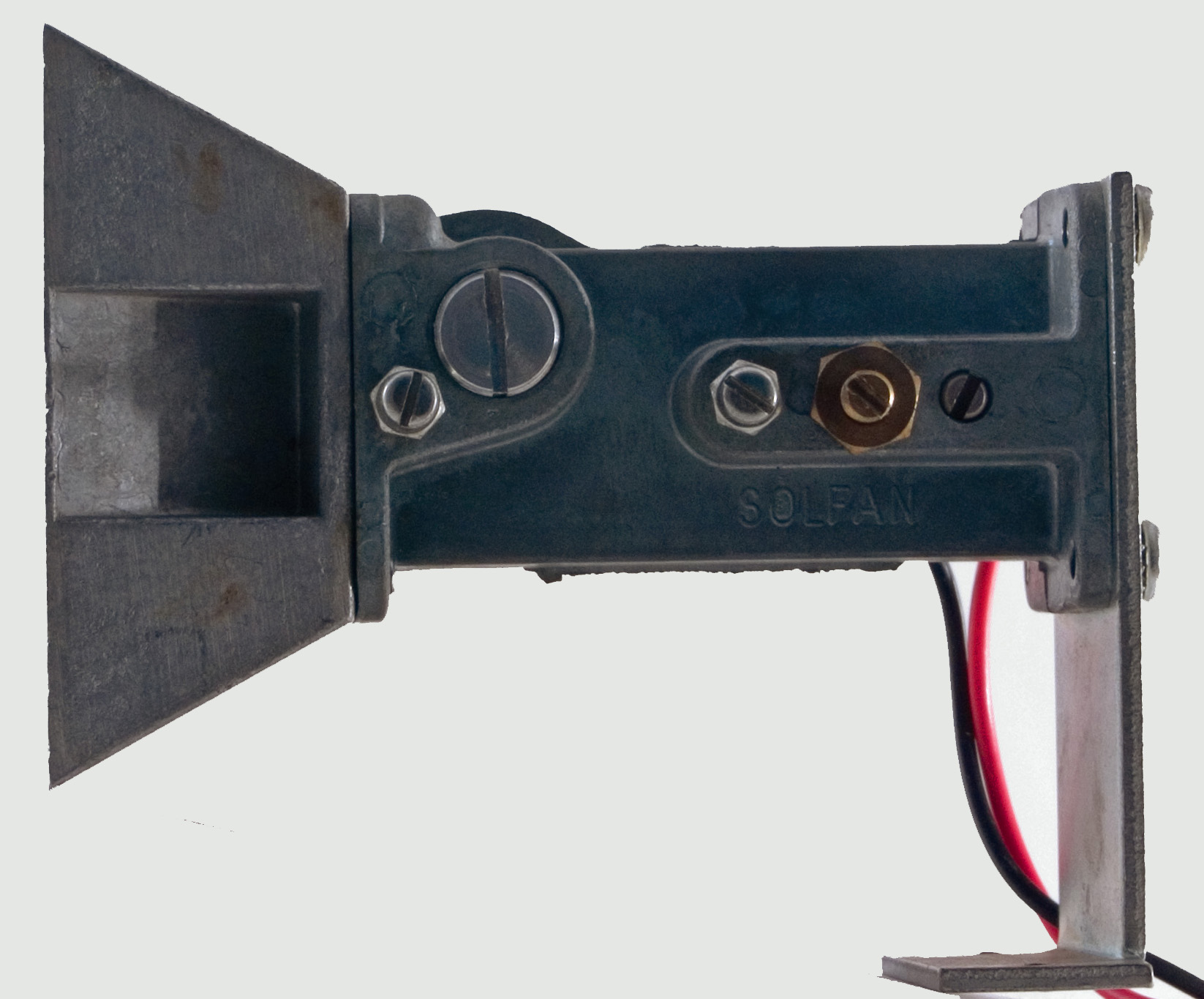
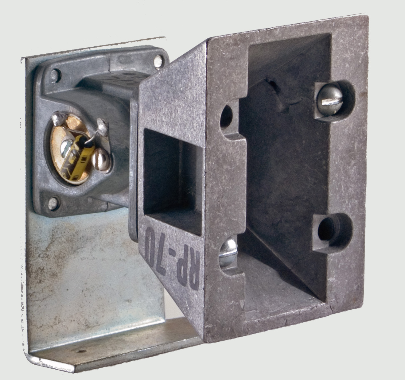
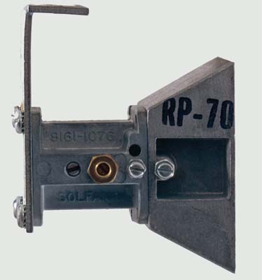
This shows the reverse side of the die-cast housing.
On the back of the casting the large nut and brass screw are the tuning adjustment mechanism. The bright plated screw and lock nut are matching components.
The mounting bracket also serves as the back wall of the oscillator cavity. Stuck to the bracket and protruding into the cavity is a piece of black lossy foam. This foam is essential to the correct operation of the oscillator and the bracket must be treated with care if removed from the back of the cavity. The casting has a central wall with fixed iris hole. The matching screw passes in front of the iris aperture.
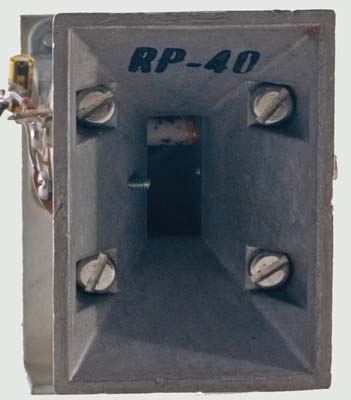
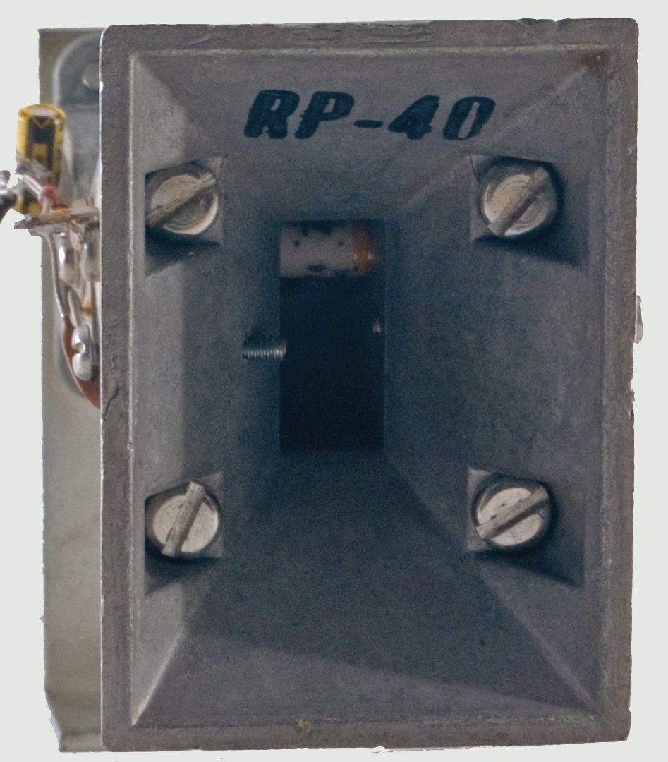
The original 6 dB die-cast horn. The fixings match standard WG 16 flange dimensions.
The original die-cast horn gave 6 dB of gain and was thus rarely of value in amateur service. This picture does show the size and position of the static sensitive Schottky barrier mixer diode.
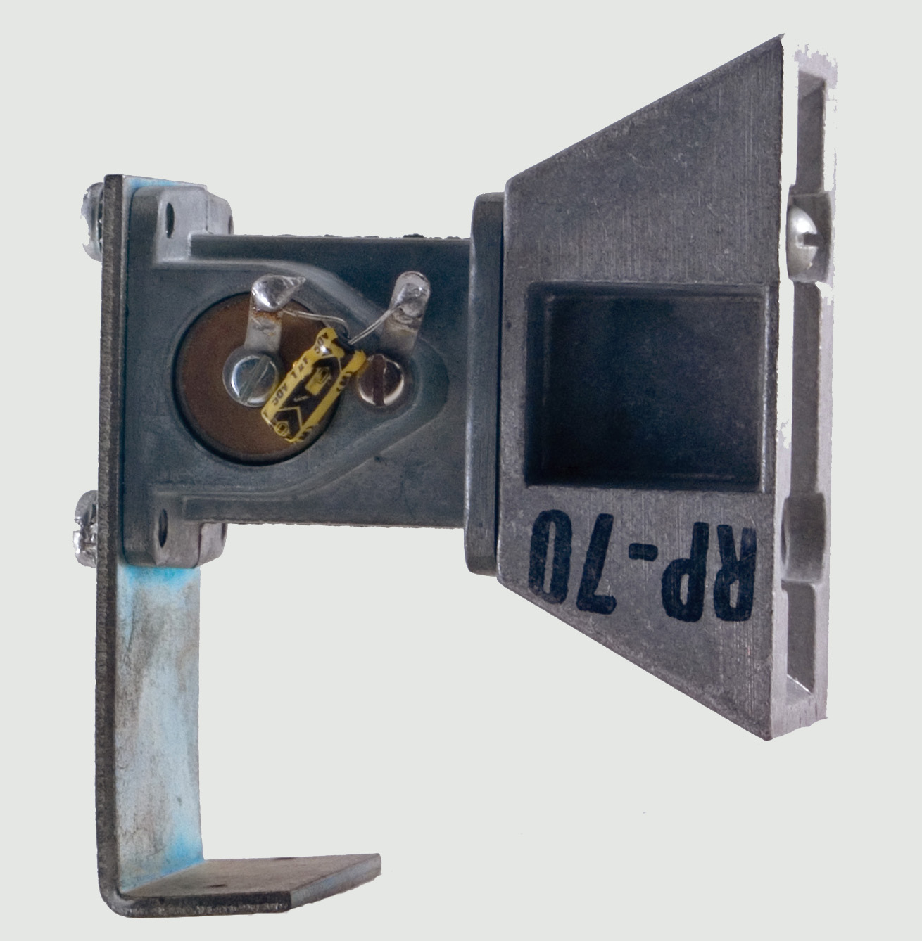
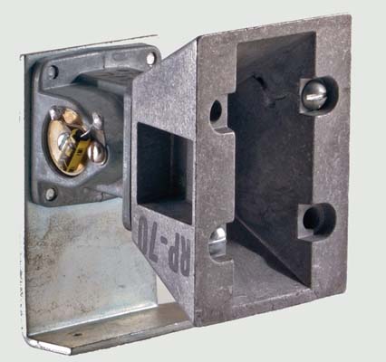
Another form of the Solfan equipment used separate modules. This is the oscillator unit. Tuning modifications as described above are directly applicable to this unit as well.
The oscillator only module found use as personal beacons and test sources as well as transmitter and transceiver units when coupled to a mixer.
The reverse of the Gunn oscillator module
The tuning screw and lock nut match the in-line unit.
The final picture shows how chunky the horns were.
The horn makes a good paper weight.
The in-line module is 100 mm long. The broad face is 28 mm and the narrow face is 40 mm overall and this also contains the device mounting, choke etc. The horn flares to 70 mm by 50 mm in a length of 27 mm.
|