|
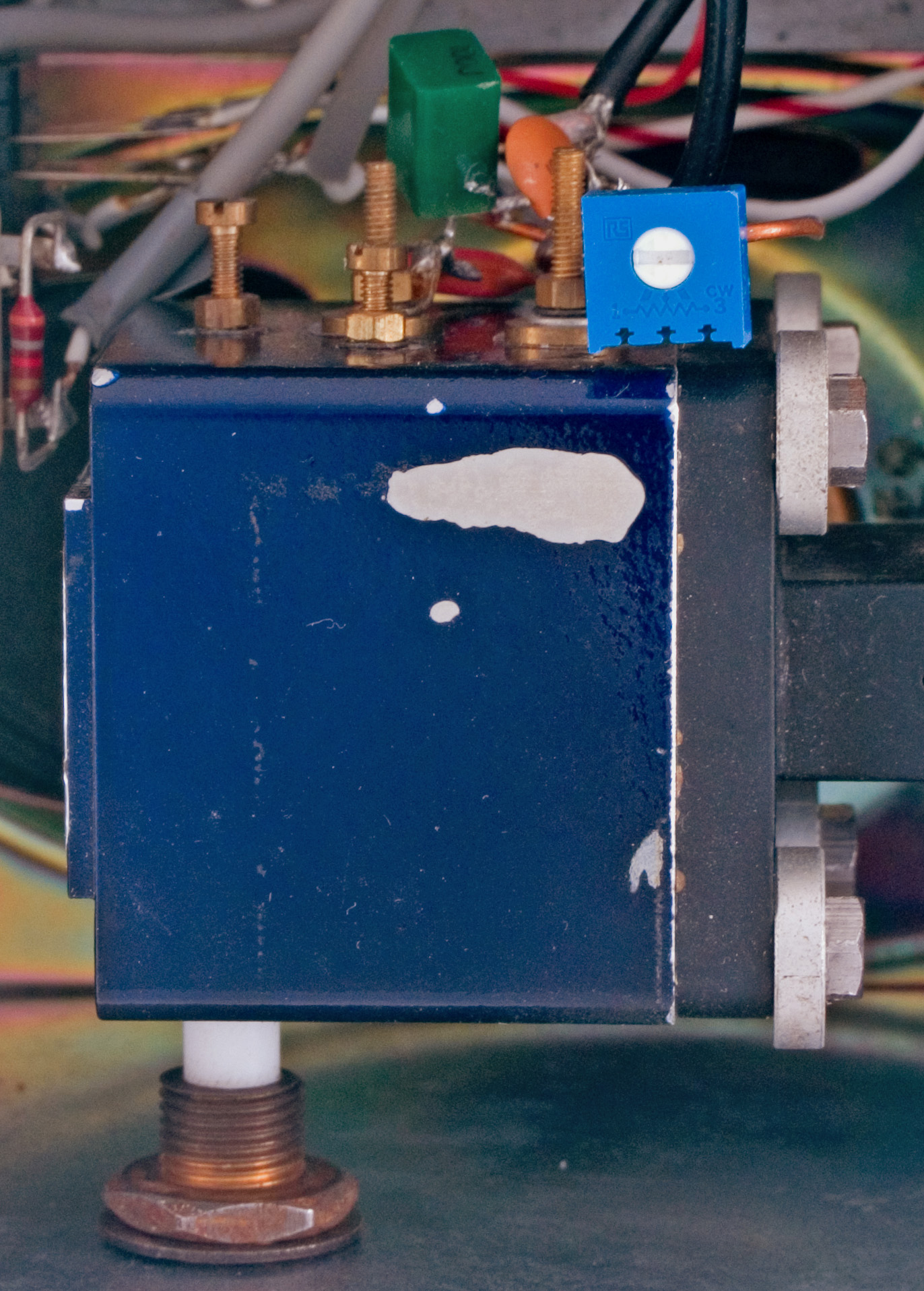
The tuning voltage control for the Band II head is a multi-turn trim-pot altered by screwdriver only so as to avoid accidental movement.
The PW EXE was published in June 1981 and immediately captured the imagination of Jack G3JMB and myself. Both of us were competent with metal working at the basic level required and both of us relished the challenge of the new band and operating technique. The project was contemplated for some time and then XYL permissions were sought and granted. Serious construction took place over the winter of 1984. We followed the construction details as presented in the PW articles. The first unsuccessful tests took place in the spring of 1985.
The 1980s were a time of the North South divide. We, in the South, all worked around 10.1 to 10.2 GHz and further North the groups used 10.4 GHz. The equipment was set for one or the other. It was only in about 2000 after we stopped using wideband equipment that I discovered that the tuning range of this equipment did cover 10.1 and 10.4. In fact the tuning rate at the lower end was 100 MHz per revolution of the tuning knob and as the PTFE came closer to the cavity wall the rate decreased markedly and it was quite a simple matter to tune in a low power narrowband beacon at 10,368.100 MHz.
Jack (G3JMB), who was retired, made contact with Ron G2DSP and Ern G8GKV and alignment tests were conducted at Steyning Round Hill. With initial success it was not long before we had a working pair of transceivers.
Maps and a sighting compass were purchased and the workings of the magnetic variation explored. With the short distances expected the bearing calculation was based on a map attached to a board so it did not blow away in the wind and a circular plastic protractor. With a pencil line on the map indicating magnetic north from the home site and another line to the distant hill the bearing was easily established.
The first proper QSOs took place from Chanctonbury Hill in mid 1985 when the pair of us were the guests of G8GKV. Operating equipment consisted of a garden chair, tripod and PW EXE, compass, protractor and a 5 Ah 12 volt gel cell battery. Ern provided talkback for us all. I think he had a low power 2 M SSB rig and something like a HB9CV aerial on a mast under three metres high.
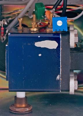
The Pascall head unit contains both Gunn oscillator and mixer diode. Between the module and the waveguide is a piece of polyester adhesive tape. This prevents air currents from changing the cavity temperature. The tuning rod is PTFE.
The components were all bought new and just as in the parts list. The Pascall 5 mW (+ 7 dBm) module looked too well finished to consider attacking with a drill. The micrometer head is still sitting waiting to be used some 20 years later. The main concern was that the module had been expensive and with two young children cash was tight. Additionally we had discovered that if PTFE screws were used a fine tuning rate was possible and this seemed like a good start point.
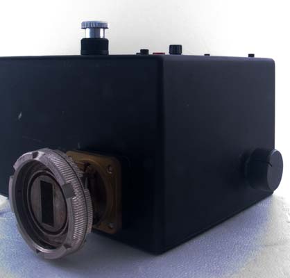
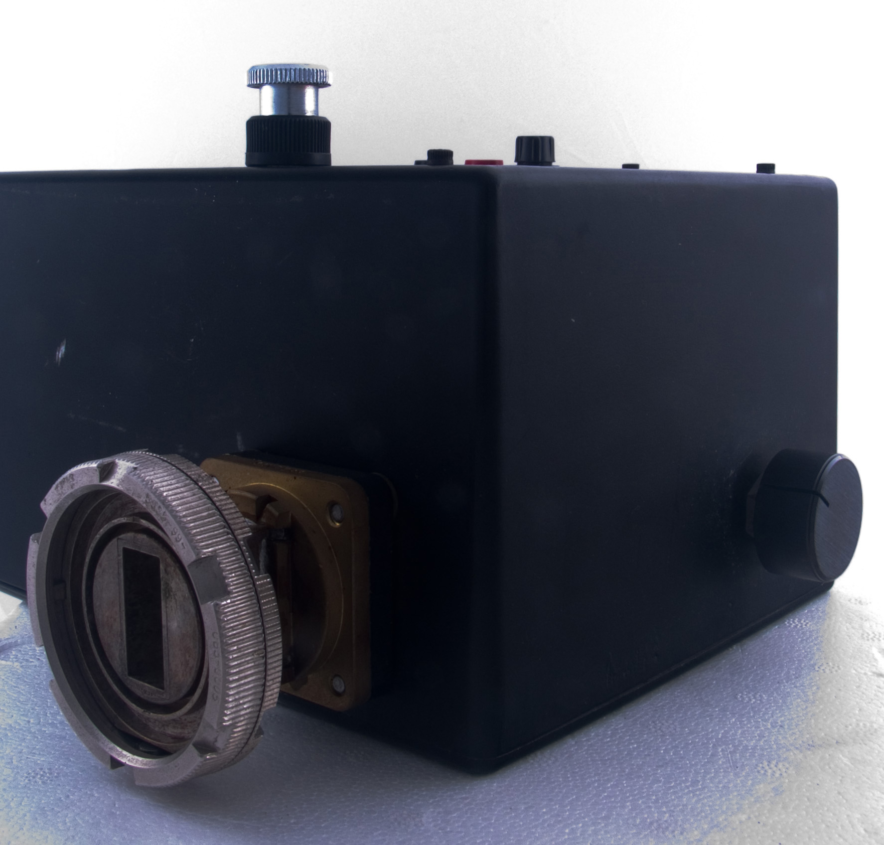
The external aspects of the 10 G section. Waveguide 16 and the tuning screw.
Jack found a source of PTFE rod ¼ in diameter and also a friendly soul who turned one end into a 4 BA thread for us. A standard ¼ bush through the die cast box and a reasonable diameter aluminium knob completed the tuning mechanism.
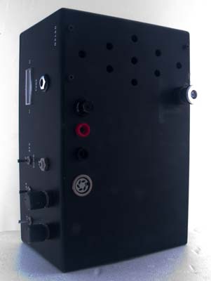
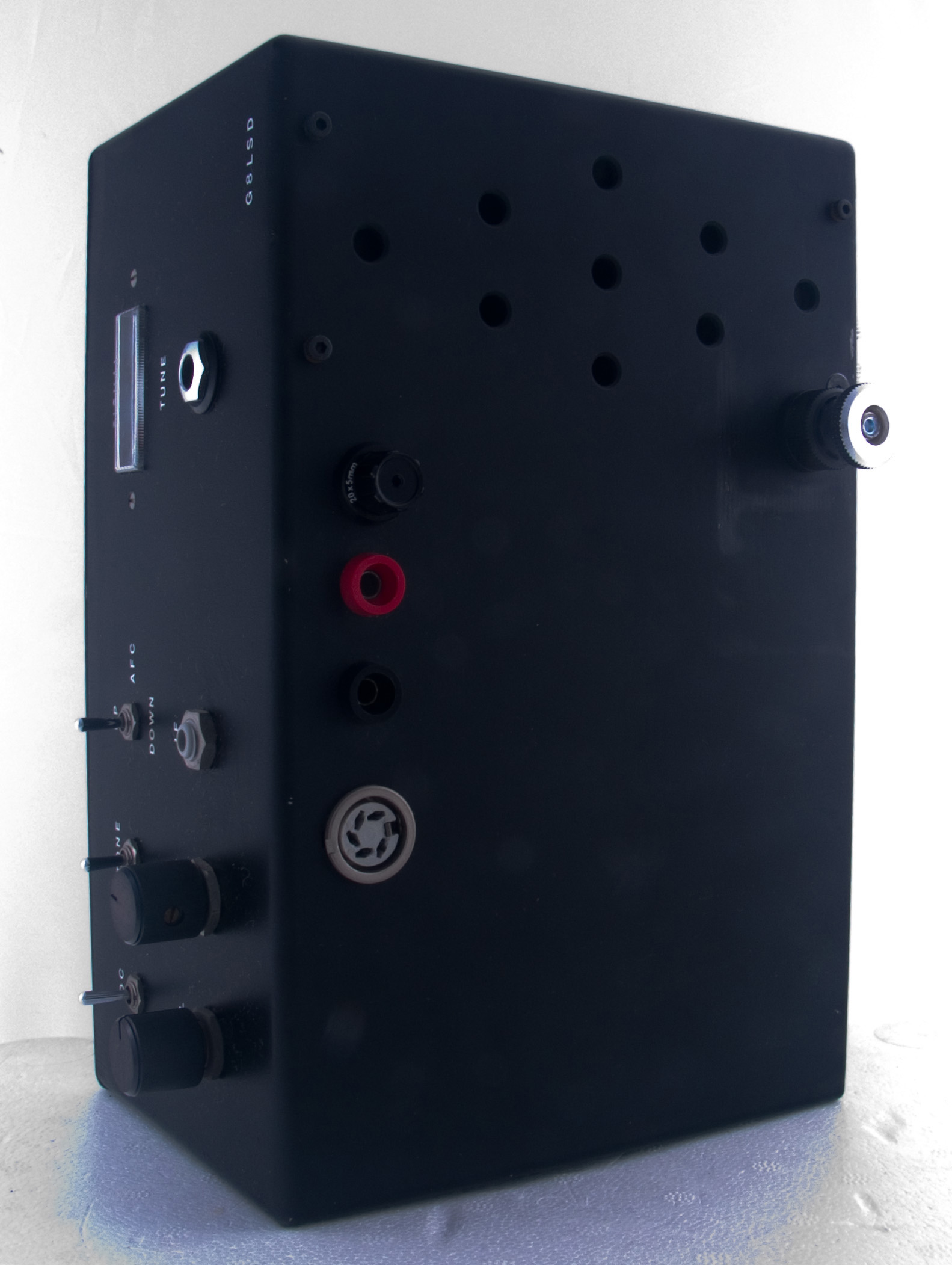
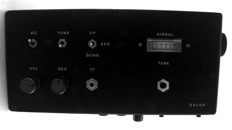
This was designed for tripod operation and possible wet conditions. The connections and speaker are therefore on the underside of the cabinet.
For some events the rain and wind kept us in the car. On other occasions the wind gusted without warning and the tripods blew over. After the waveguide was put back into alignment in the dish a set of guy cords and tent pegs were purchased to stop it happening again.
The lack of frequency stability made a wide bandwidth essential and WB FM gives excellent audio quality. The problem is that for low level signals almost nothing is detected and at a threshold value the audio becomes excellent and remains so. The S meter only rarely moved across the scale even though the copy was good. A reading of 2 on the scale was a good signal. 9 or more could be expected from stations a few km away.
To get extra points one could move sites and for a couple of years I would go to Beachy Head at the start of the activity period and then move back to Chanctonbury (IO90TV34) at lunchtime. In all I used quite a few sites and greatly enjoyed the fun of hilltop to hilltop working.
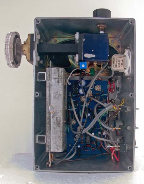
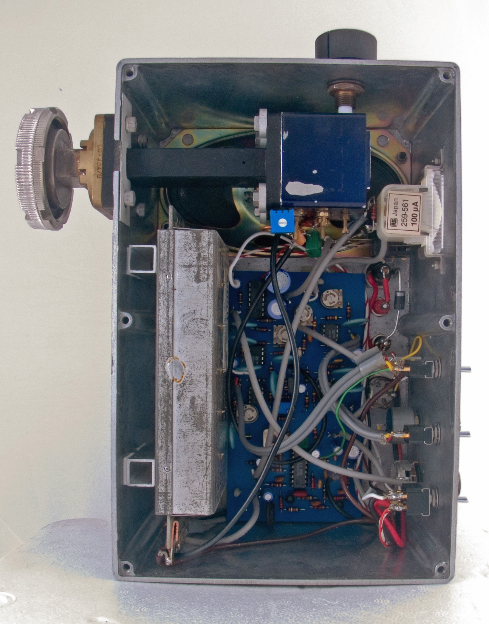
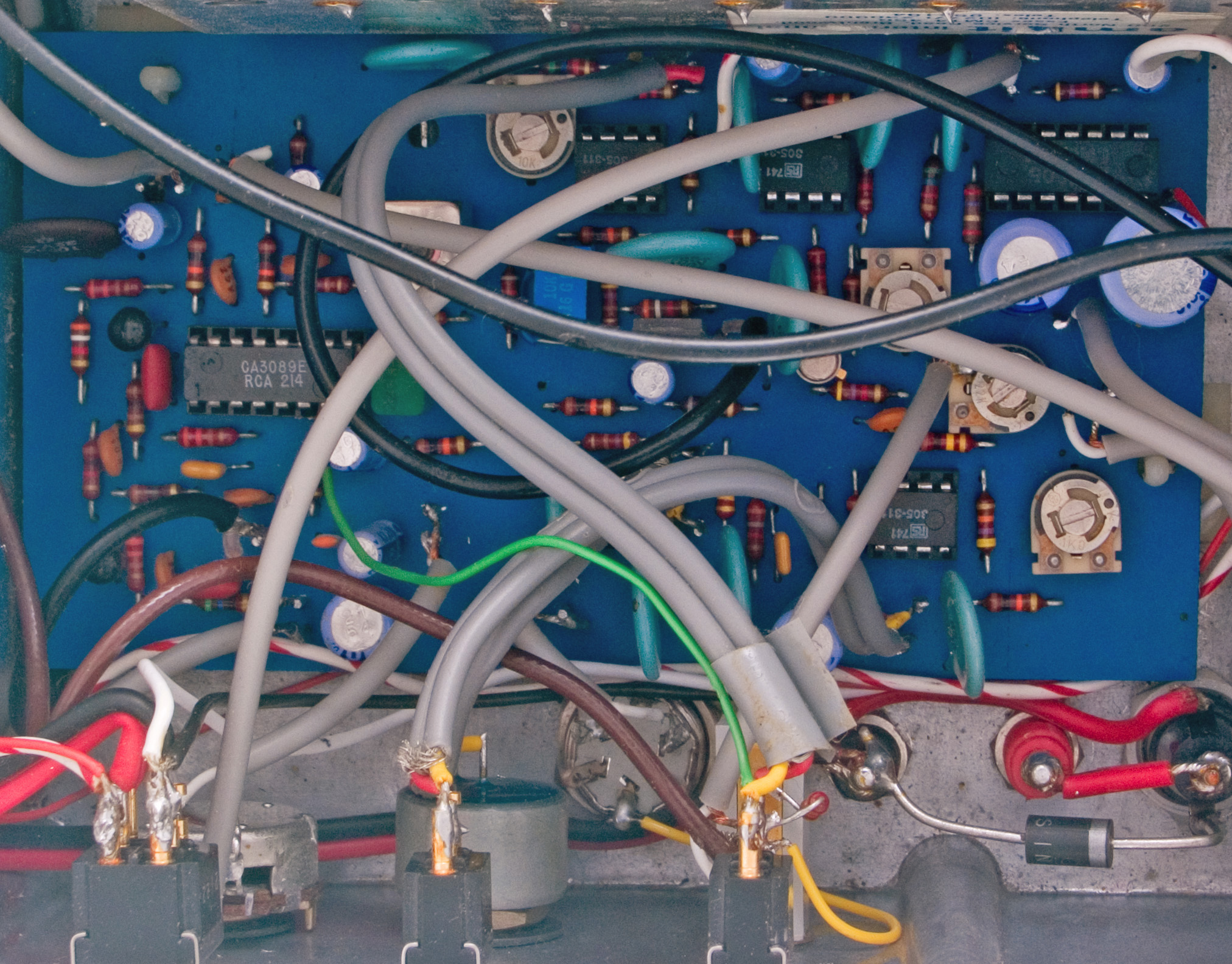
The inside layout of the PW EXE. All earth connections to the Band II tuner module are made to a plated copper buss-bar.
The PW EXE inside its metal case was more stable that one might suppose. The standard way of working if two sets of gear had the same 100 MHz IF was full duplex. One station transmitting 100 MHz above (or below) the other. As the modules housed the mixer diode in the same cavity as the Gunn source the transmitter and local oscillator were one and the same. The mixer diode placing in the cavity gave the correct injection level. As a free running Gunn oscillator would drift in frequency the electrical tuning ability of the device was exploited by building in AFC. Only one station could use AFC during a contact.
Activity days were relaxed affairs and one lunch time when I was operating at Ashdown Forest I had made contact with Ian G8KQW some 20 km distant on Ditchling Beacon and we left the rigs on while we had lunch. In all the rigs stayed locked for the whole of the 50 minutes and never required re-tuning.
The first contact of over 150 km took place in 1987 with a contact across the channel to Albert F6WN at a distance of 175 km. That was a great day as we had waited ages for the right conditions to exist and we could see the tell tale signs of a brown band on the horizon that indicated the possibility of a duct forming.
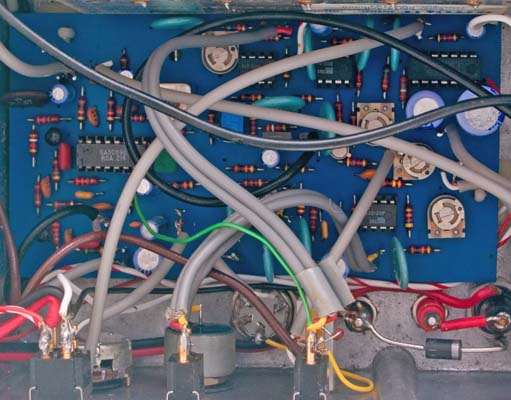
The board was supplied by PW pre drilled and was a joy to assemble.
The best ever DX with the 5 mW of the PWE EXE was unexpected. Jack and I had gone to Beachy Head to try and work Chris G0FDZ on Guernsey with about 150 mW of narrowband SSB. The QSO was end stop and we began experimenting with open waveguide at either end. Still solid copy! Chris then asked if we had brought the wideband with us. I said no, but then I spotted a brown leather case in the boot of the car. I had been helped to load up by Mary, my XYL, and she had just put all the gear in the car including the wideband. The gear was mounted on the tripod and suddenly we had a 248 km contact. Fantastic.
The die-cast box housing the PW EXE measures 220 x 145 x 105 mm. At the waveguide side the circular WG 16 flange extends 40 mm from the box.
|