|
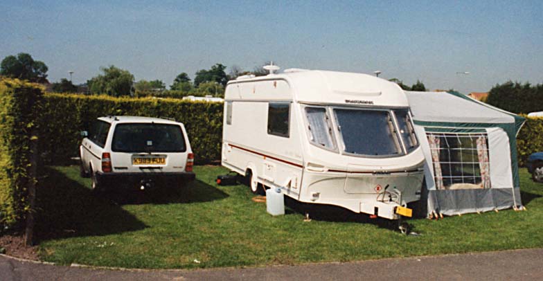
Base camp outside York some 50 miles south of the Cockayne Ridge.
This operating Sunday in May 1997 amounted to a mini DX-pedition. The operating Sunday was part of a family holiday and all of the equipment had to travel the 240 miles from Sussex. After driving to York on the Saturday, we explored the North York moors in the early evening to find a site. We decided on this site on the Cockayne Ridge.
We set out early on the Sunday with our two daughters and sufficient entertainment so that I could spend all day operating. The equipment required for a day of 10GHz narrowband operating included:
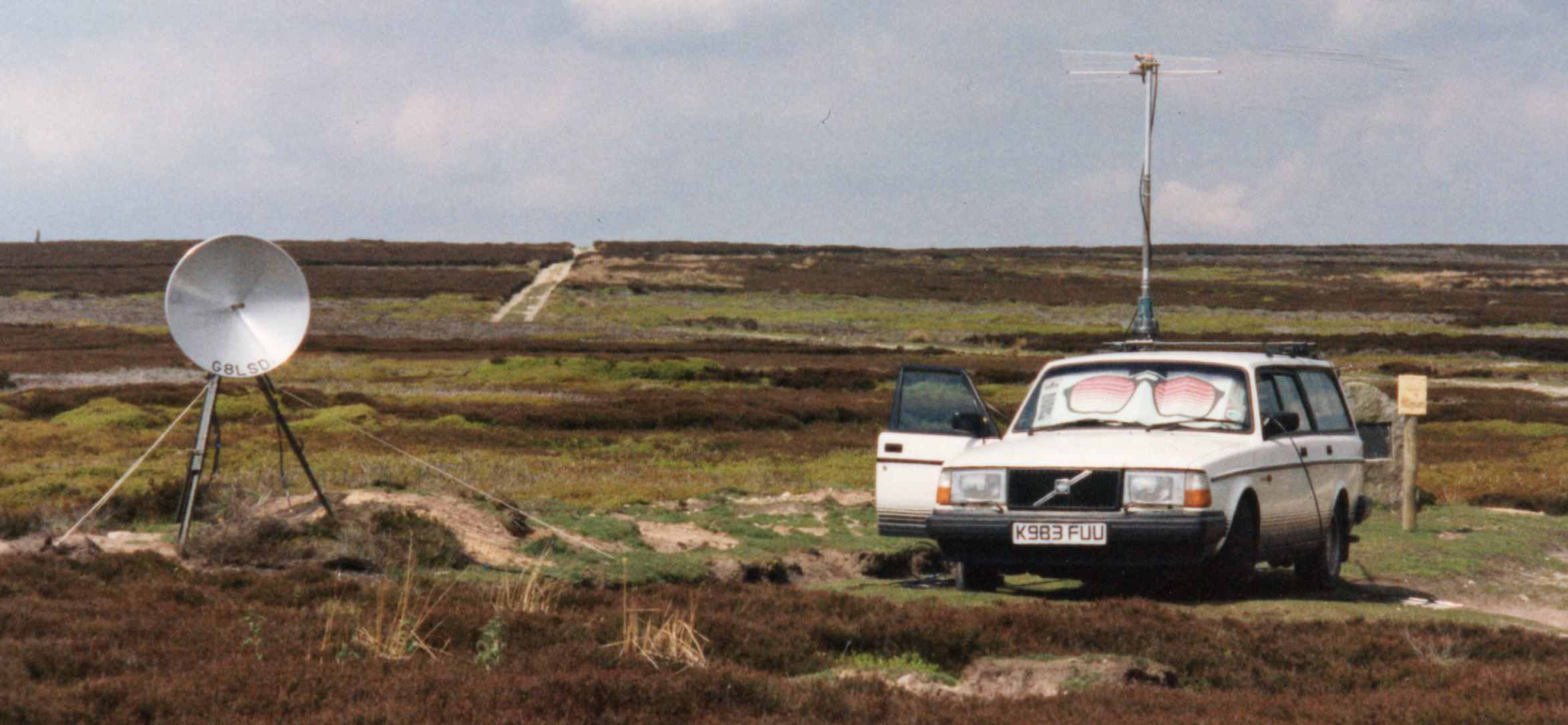
- 80 cm dish with penny feed on waveguide 16. Measured as 34.5 dB gain.
- Sturdy tripod (ex military) with guys.
- Dish rotator.
- 10 GHz transverter head unit.
- Umbilical cord for head and rotator. 15 metres.
- 144 MHz tuneable IF and control centre.
- Headphones and morse key.
- DSP audio filter.
- 144 MHz taklback system and 9 element yagi.
- 432 MHz talkback system and 9 element yagi.
- Medium duty aerial rotator and three pole mast.
- Computer for bearings and distance calculations.
- 4 Heavy duty lead acid batteries giving 48 volts.
- Switch mode DC-DC power converter for stable 13.8 volt supplies.
- 12 Volt to 240 Volt AC inverter for driving rotator and computer.
- Test equipment, tools and log sheets, sighting compass etc.
- Finally all connecting leads and a microphone or three.
All of the equipment was packed in storage boxes for transport and a check-list to ensure all was packed was essential. If anything was left behind the whole day could be ruined. It was normally something significant that was not picked-up and never a trivial item. On one outing the missing item was the main tripod. It was surprisingly easy to do.

The operating site with the dish separate from the car.
The microwave head was built into a die-cast box and each module was built into a tin-plate box. The box within a box technique being the established style of construction. The basic units were the SSB electronics modules that were acquired late in 1987 and operational with 160 mW for the 1988 season. Over the years the G3WDG modules were added to provide a HEMPT pre-amp and two stage pre-amp with filters. On the TX side the failing output from the SSB units (down to 50 mW) was boosted to 200 mw and then to 980 mW. To protect the pre-amplifier from excess RF input if the relay is slow to change from transmit a sequencer unit is included in the head unit. The PTT line in the 144 MHz driver rig is cut and routed up the umbilical to the sequencer. The final act of the sequencer in going to transmit is to route a go-TX signal back down the umbilical to switch the Trio 751E into transmit.
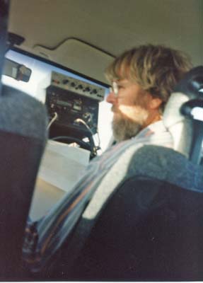
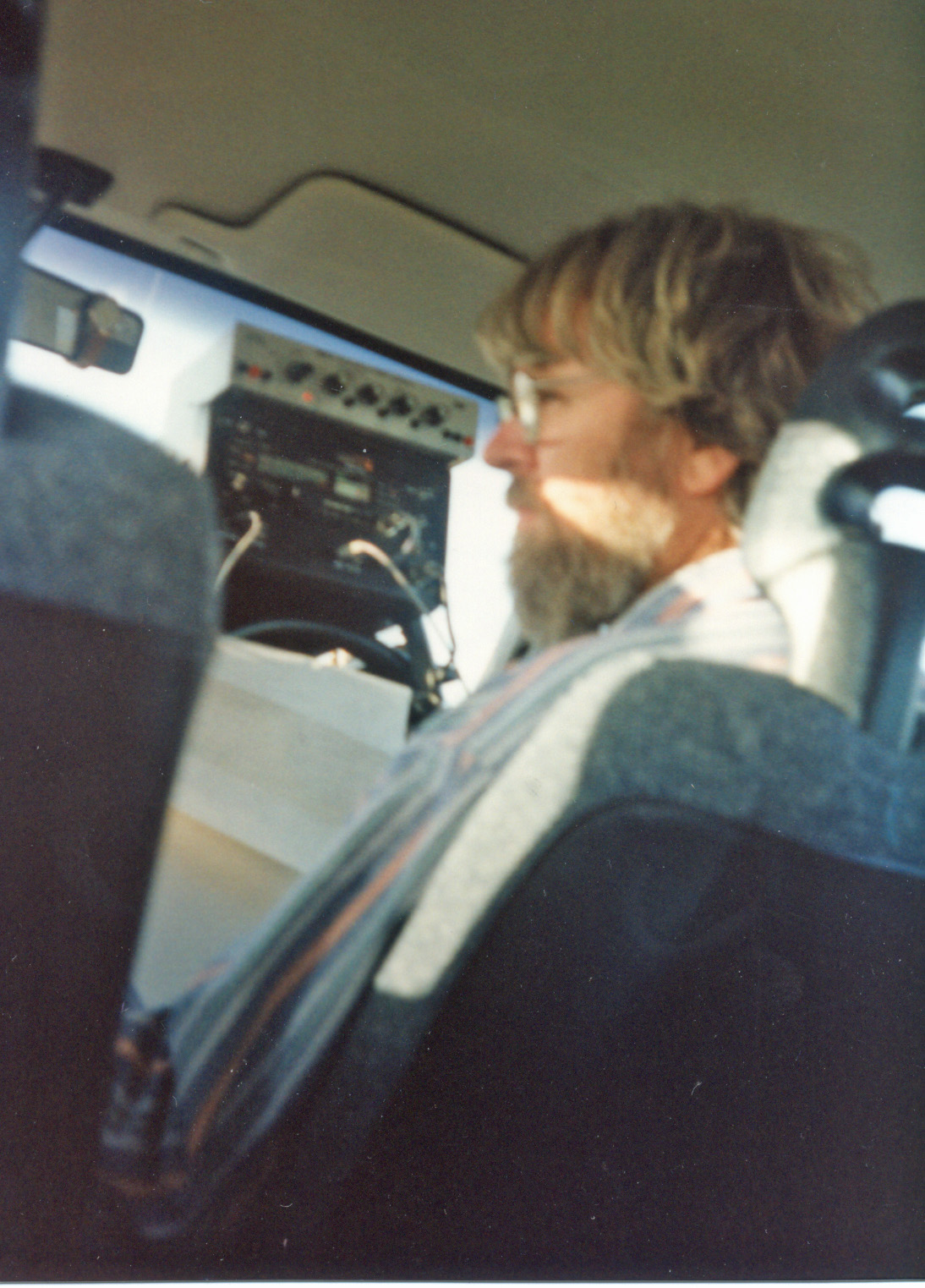
The operating position in the driving seat.
Looking at the operating position: the microwave control unit is resting on the steering wheel. The Trio 751E 2m multimode rig drives the 10 GHz station. Also in the box is the counter for the dish rotator. The rotator itself is a hand turned, worm driven, journal bearing device originally made for the military. This was motorised by replacing the handle with the motor from a 3.5 Volt electric screwdriver to provide sufficient torque. The fixed drive incorporates a wheel with 45 fine hack-saw cuts in the circumference. With 80 turns on the worm for one complete rotation this gives 3600 pulses per revolution. A direct up/down counter module provides the read-out. The MFJ audio DSP filter is sitting above the control box.
On the dash board is the 791 70 cm rig and 50 Watt BNOS amplifier. The rear-view mirror is a convenient hook for the GMT watch and the headphones.
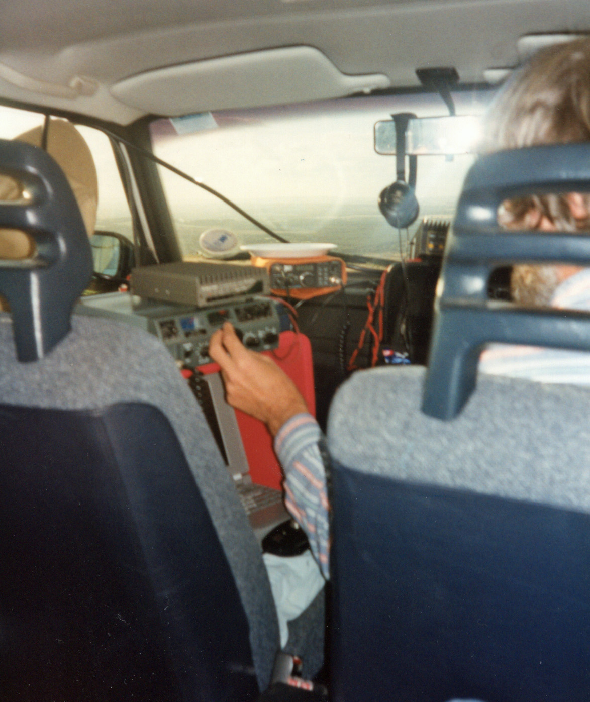
The passenger seat well has two plastic tool-boxes each with two 12 volt sealed lead-acid batteries. All four rescued from an industrial UPS when planned maintenance changed all 20 batteries. A switch-mode DC-DC converter takes the 50 volts and delivers a clean 13.8 volt supply for the rigs. The seat has a 12 to 240 AC inverter to run the computer and roof-top rotator, it also doubles up as a support for the board on the seat to give a level platform for the computer and talk-back. The plastic storage tub used for transporting the gear supplies the top shelf to mount the 144 MHz talk-back ststion. A Yaesu FT7 HF rig feeds a Microwave Modules transverter and then to a 40 Watt PA.
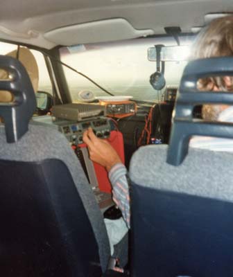
With two sheets of contiboard the passenger seat becomes a two tier side table.
By looking out the site the day before a selection of landmarks had been identified as well as obtaining permission to operate from the land owner. Before setting out the landmarks were identified on the map and their NGRs noted. When setting up on site, a chosen landmark was sighted across the face of the dish. The dish then pointing 90 degrees away from the landmark. The bearing evaluated in the computer would then be entered into the dish rotator readout. Due allowance being made for the 90 degree mis-pointing of the dish. With the dish thus set-up the day could commence.
The day went well and below is the log for the 10 GHz station of G8LSD. The objective was to achieve 400 km or more and this was achieved.
freq MHx | Mode | Station | Time | RST Sent | RST Recd | Locator | DX km |
10368.1 | J3E | G3PHO/P | 09:18 | 5/9 | 5/9 | IO94KF50 | 17 |
10368.1 | J3E | G4FCD | 09:30 | 5/8 | 5/4 | IO91KX | 264 |
10368.1 | J3E | G0HNW/P | 09:44 | 5/9 | 5/9 | IO93CH | 126 |
10368.1 | J3E | G3OZI | 10:28 | 5/3 | 5/6 | IO93FL | 103 |
10368.1 | J3E | G3PYB | 10:42 | 5/4 | 5/3 | IO91VX | 270 |
10368.1 | J3E | G8DKK | 10:49 | 5/6 | 5/6 | IO91VX | 270 |
10368.1 | A1A | G3GNR | 12:04 | 3/1/9 | 5/5 | IO70WT43 | 223 |
10368.1 | J3E | GW3UKV/P | 13:12 | 5/5 | 5/4 | IO83KB | 198 |
10368.1 | J3E | G3NEO | 14:05 | 5/6-2M | 4/4 | IO9311 | 58 |
10368.1 | J3E | G4BRK | 14:32 | 5/7 | 4/3 | IO91DP | 304 |
10368.1 | A1A | G4ZXO/P | 14:55 | 4/1/9 | 5/1/9 | JO00BU00 | 400 |
10368.1 | J3E | G3KEU/P | 15:16 | 5/5 | 5/3 | IO91GI | 335 |
10368.1 | J3E | G3FYX/P | 15:17 | 5/5 | 5/3 | IO91GI | 335 |
10368.1 | J3E | G4FXW | 16:08 | 5/8 | 5/7 | IO93II84 | 113 |
10368.1 | J3E | G3JMY | 16:55 | 4/1 | 4/1/9 | IO81RM | 330 |
|