|
Since the full design of the G3JVL 10 GHz transverter was published (RadCom, April 1980) a number of these units have been built and are operating successfully. However, one area which has caused difficulties in some cases concerns the tuning up of the device. This is due to the large ratio of the mixer diode impedance to that of the waveguide, which makes the settings of the six matching screws between the diode and the waveguide filters rather critical. In response to this, G3JVL has produced a modification which eliminates the need for these matching screws and thus makes this unit very much easier to tune up.
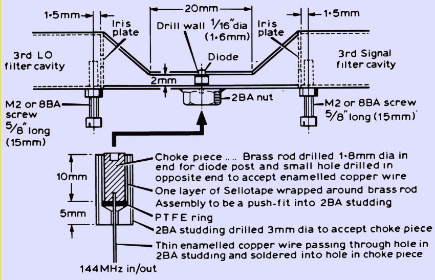
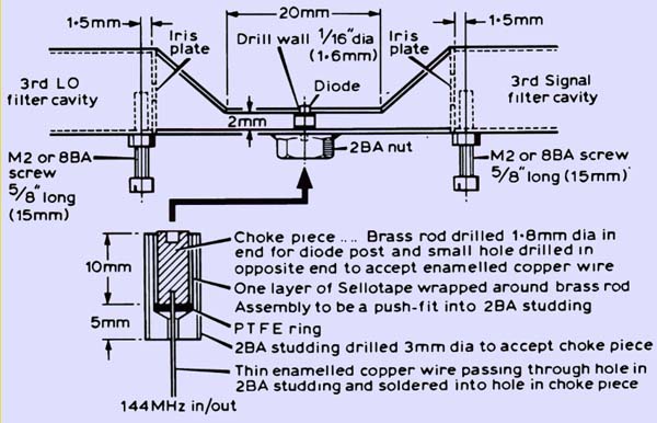
The modification entails removing one of the broad walls of the waveguide in the centre section of the mixer, and replacing it with a specially bent-up piece of metal, as shown above. The tapering sections of the waveguide thus produced perform the impedance matching between the full height waveguide and the mixer diode.
The material used for the tapering section is made from a piece of brass or copper of similar thickness to the waveguide wall, ie 0.048 or 0.050 in. The broad wall of the waveguide on the underside of the mixer (ie the side carrying the 2 BA nut as originally specified) should be removed, eg by drilling a number of small holes close to each other and then using a needle file to remove the metal between them, followed by filing down the rough edges. The tapered section should then be inserted (it will hold itself in position if left slightly oversize on the 0.9 in dimension). Prior scribing of lines on the inside narrow walls of the waveguide using a suitable thick piece of metal as a guide, held against the remaining broad wall, will act as an alignment aid for determining the correct position for the tapered section. Turn the unit upside down, and mark the position for the 0.063in hole in the tapered section by drilling very slightly into the metal using a 0.094in drill (in a vertical drilling stand) fed into the waveguide through the 0.094in hole in the opposite wall of the waveguide. Remove the tapered section, drill out the 0.094in hole in the waveguide to 4 mm diameter, and tap this hole 2 BA. The tapered section should then be drilled 0.063in in the marked position. Drill and tap the M2 (or 8 BA) holes next to the iris plates in the waveguide cavities, and be careful to remove the swarf as far as possible by tapping the metal out of the iris holes into the centre section.
Refit the tapered section into the waveguide and assemble a 2BA brass nut on to a 2 BA tap or an old brass screw (which will not take solder easily), and jig the 2 BA nut hard up against the wall of the waveguide. The whole waveguide assembly is then heated on a hotplate to just below solder melting temperature, and the tapered section and 2 BA nut soldered into position using an iron to provide the final heat. Be careful not to overheat the unit, or some of the previously-assembled pieces may fall off!
When the unit has cooled down, the diode may be placed into the newly-made choke/choke-holder assembly and fitted into position. The thin enamelled copper wire is connected to the changeover relay in the preamplifier box. Try to keep this wire as short as possible.
The tuning-up of the unit is carried out exactly as described previously, except that no matching screws should be needed in the centre section. The newly-fitted M2/8 BA screws are adjusted for maximum power transfer through the cavities when the cavities have been tuned to resonance. Their presence will affect the tuning of the cavities slightly, and some small degree of cavity retuning will probably be necessary as they are adjusted. Final adjustments of all screws should be made for best noise figure or maximum power output (or a compromise between them) as originally described.
As an alternative to bending up the metal for the tapered centre section, G3JVL suggests that, if milling facilities are available, the centre section would usefully be made from a solid piece of metal. The fixing for the 2 BA choke/diode-holder assembly would then be simply a tapped hole. The block of metal could be either soldered or screwed into position. This would enable the modification to be carried out without the need for any further soldering.
|