|
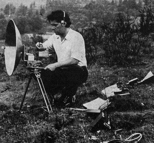
GM3OXX seen operating his 3 cm portable gear. This is the equipment which achieved the British 3 cm record distance of 243 km in early 1975. Note that the dish is fed with a dipole feed. The horn on the right is connected to an even smaller 3 cm transceiver that is described below.
Introduction
This article describes what is probably the simplest and most economical means of transmitting and receiving signals over considerable distances on the 3 cm band (10,000-10,500 MHz). As is usual, results depend on the aerial with which the transceiver is used. With a small horn having a gain of 15-20 dB, optical distances of 50 km or better can be expected, while if a paraboloid of around 30 dB gain is used the equipment is capable of distances exceeding 150 km, which will earn the user the Microwave Distance Award. The transceiver is so small that it can be held in the hand and carried to normally inaccessible mountain tops. For use over short distances hand-held operation is perfectly feasible, but for serious DX a stable support such as a light tripod or mast is recommended. The equipment is powered from a 12V DC battery of 2 Ah capacity which provides a minimum of 10 hours' continuous running.
This little transceiver surprised its builder and has delighted the remainder of the GM microwave group. It was a pleasure to see it working, first over modest distances, which gradually increased until finally it earned its owner Microwave Award No 14 for a 2-way contact of 163 km when using a 2 ft dish aerial.
Basic System
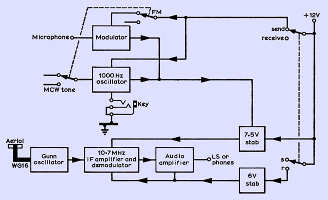
Block diagram of the 3 cm transceiver.
A simple block diagram of the transceiver is shown above. An X-band Gunn oscillator functions in the dual role of transmitter and self-oscillating mixer. When in the transmit mode the oscillator is frequency modulated by a 1,000 Hz tone for test, alignment and mcw, or by a modulator for speech. Deviation of up to 1 MHz is produced. On receive, signals 10.7 MHz away from the oscillator frequency are selected by the fixed-tuned high-gain FM IF strip and demodulated. After audio amplification the modulation is heard in a small loudspeaker or headphones. The tone oscillator can be used on receive as an aid in reception of MCW and unmodulated signals. A stabilized power supply produces 7.5 plus or minus 1V for the Gunn oscillator alone. The IF and AF amplifiers are powered by 6V derived from a separate simple voltage stabilizer.
Circuit Description and Notes
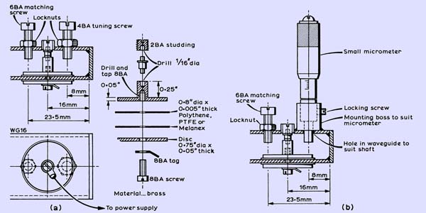
(a) The GM8BKE design for a simple fixed-frequency Gunn oscillator. (b) The GM8BKE design modified for continuous tuning using a small micrometer.
The Gunn oscillator above is to the GM8BKE design, with minor improvements. Experiment has shown that the matching screw should be positioned 3λ/8 (7-5 mm) in front of the Gunn, and a 6 BA screw is now preferred to the 4 BA screw originally specified.
While fixed-frequency operation is possible it lacks flexibility unless a tunable IF is used. A marked improvement in operating convenience results from making the Gunn oscillator tunable, thus providing the facility of being able to tune the receiver to the frequency of any transmitting station. Accordingly (Fig 2(b)), a small micrometer replaces the 4 BA tuning screw. Although this may seem a trifle crude it certainly works and the tuning rate is not unduly rapid. Once netted, small corrections of plus or minus 5 MHz are made by adjustment of the voltage-setting potentiometer in the stabilizer power supply. The frequency stability has been found to be more than adequate without the need for AFC. This is the outstanding feature of the GM8BKE design.
The RF output of the X-band Gunns, currently advertised in Radio Communication, (believed to be CXY11 or equivalent) is nominally 10 mW. However, spread in production results in devices which will deliver more than twice that; at the same time others will only produce about half. Since most constructors will wish to have a spare Gunn in case of emergency there is a good chance that one of the two will produce at least 10 mW. The DC input to the oscillator is approximately 1 W (140 mA at 7V), giving an efficiency of around one per cent which is comparable with that of a small klystron.
A Gunn device will not survive a reverse supply connection, and it is therefore essential that the constructor should avoid an expensive accident by being able to recognize the polarities of the two stud connections. An enlarged drawing of a Gunn is shown.
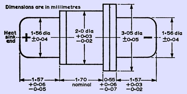
Correct polarity should also be observed if it is ever found necessary to measure the DC resistance (about 50 Ohms). Beware particularly of certain multimeters which use internal batteries of up to 22V on ohms ranges.
The modulator, tone oscillator and power supply require little comment, being to the G3ZGO design. The voltage-setting preset potentiometer can be brought out as a manually adjustable control for fine frequency tuning when netting.
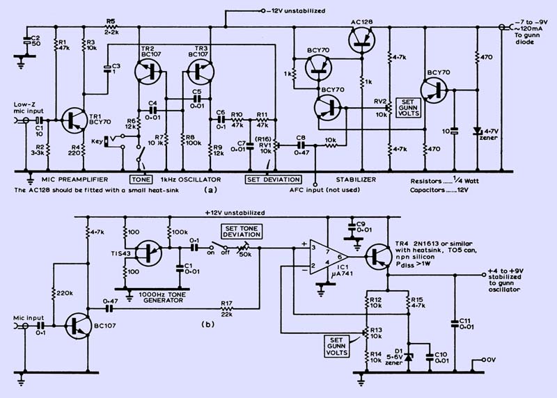
Combined modulator, tone oscillator and PSU circuits suitable for use with the 3 cm transceiver. For greater safety, precautions should be taken to protect the transceiver from damage due to supply reversal. To protect the Gunn oscillator, connect a zener diode rated at approximately 0.5 V above the maximum working voltage across the DC supply line to the oscillator. Component references are keyed to layout (b) shown below. (a) A positive-earth modulator/PSU by G3ZGO. To obtain negative earth reverse the polarities of zener diode, electrolytics, and substitute NPN transistors for PNP types and vice versa. A fixed resistor of 10 kΩ replaces RV1 as shown in the component layout diagrams. (b) A negative-earth modulator/PSU for a low-power Gunn oscillator after G8CGN. Change C1 to alter tone frequency. Change R17 to vary deviation on speech.
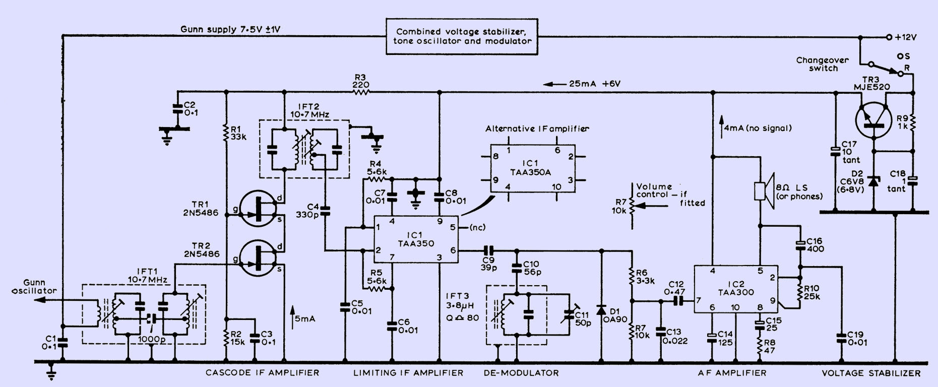
On receive, the Gunn operates as a self-oscillating mixer. When used as a mixer a Gunn will be noisier than a microwave diode but not by so much as to be of great consequence. Ideally, the device should be selected for optimum performance as a low-noise mixer but the majority of constructors will have little choice in this. Experience shows that Gunns which oscillate normally function satisfactorily as self-oscillating mixers. The untuned primary winding of the first IF transformer (below) is connected in series with the 7.5V supply line to the Gunn oscillator and signals at 10.7 MHz are selected by the double-tuned bottom-coupled circuits. Some 20-25 dB gain is supplied by the cascode-connected pair of 2N5486, 2N5245, TIS88 or equivalent, whose source current is set to about 5 mA by adjusting the 220 Ω resistor in the supply line. A second double-tuned transformer is used to couple the amplified signal to the TAA350 limiting IF amplifier.
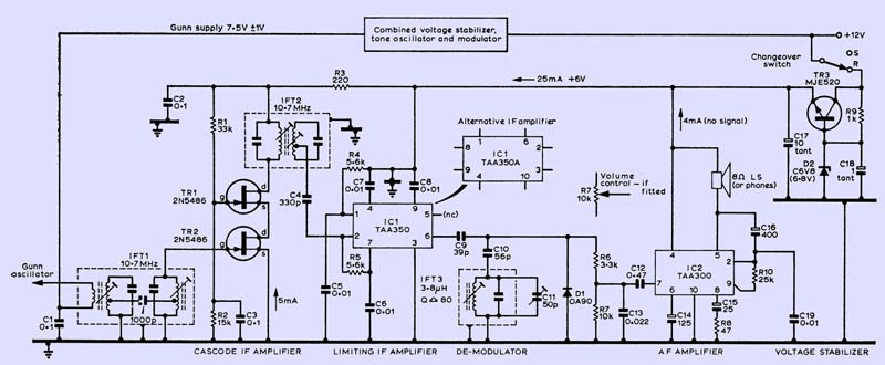
The receiver IF and audio circuit diagram. R10 should be selected to give 4-5 mA standing current. Note that this circuit has a negative earth. Suitable alternatives for TR1, TR2 - 2N5245 or TIS88.
Note that the TAA350 may not now be generally available, having been superseded by the TAA350A. The two are identical except that the connections have been rotated by three on the TAA350A. The amplifier has a matched power gain of typically 80 dB and limits at 100 μV input. Demodulation is effected by a simple slope detector. Though no snags have been encountered by the author, it should be noted that the TAA350 is a high-gain device and care should be taken to see that no earth-return currents from the output get back to the input, otherwise the device will oscillate. So keep IC leads and decoupling capacitor leads as short as possible. The inductor for the slope detector should comply with the manufacturers' recommendation if top performance is to be achieved.
No volume control was fitted on the box, as it was found that due to the TAA350's input limiting of typically 100 μV the recovered audio just drove the final audio amplifier to a comfortable level. However, a volume control can easily be fitted by changing R7(10 kΩ) for a 10 kΩ potentiometer. The IF and AF amplifiers are operated from a stabilized 6V line provided by a simple stabilizer from the 12V supply. Although an MJE520 is quoted, practically any small NPN power transistor would do this job, such as a 2N3053. Changeover from receive to transmit is accomplished by means of a miniature toggle switch. The Gunn oscillator runs continuously. The total drain from the 12V supply is approximately 200 mA on transmit and 240 mA on receive.
Construction Details
Only general guidance can be given because so much depends upon the expertise of the constructor and tools and facilities available to him.
The Gunn oscillator is constructed in brass WG16. If either oscillator is selected these dimensions can be used with confidence except, as noted earlier, the matching screw is positioned 7.5 mm in front of the Gunn and a 6 BA screw is preferred.
If a tunable Gunn oscillator is required, the size of the micrometer mounting boss will depend on the size of the micrometer available. In any case the boss outside diameter cannot exceed approximately 12 mm. The constructor is advised to have the boss turned down and drilled on a small lathe. Brass rod of ½ in diameter will generally be suitable and if the job cannot be done within the local amateur fraternity most small engineering concerns will oblige for a modest fee. A hole a few thousandths of an inch larger than the micrometer shaft where the tuning screw was originally located must now be drilled.
The micrometer should be inserted in the mounting boss so that the shaft enters the hole and thus locates the boss for soldering. Set and lock the micrometer so that approximately ¼in of the shaft enters the waveguide. The mounting boss is soldered to the waveguide and solder is built up around the bottom edge to give as strong a joint as possible. A soldering iron of some 100-200 W rating is essential for this job which must be done before the back plate is soldered to the waveguide to seal the cavity. Ensure that the waveguide mounting boss and back plate are shining bright and perfectly clean before soldering, or dry and weak joints will occur.
A further refinement is to terminate the waveguide cavity with a solid, tight-fitting block instead of a soldered brass plate. The block can be slid in or out to set the oscillator frequency and power peak, then fixed by a set screw, solder or adhesive. If this suggestion is adopted the cavity length should be increased to allow for the depth of the block.
With the dimensions quoted, a power peak will be obtained at the bottom of the band, say around 10,000 MHz. If it is much lower than this point the back plate can be removed and a few thousandths of an inch taken off the end of the waveguide, using a smoothing file, and the back plate replaced. As this is very much an empirical operation, due care should be taken or the power peak will go too high. In this event it would be better to advertise for QSOs on 10,368 MHz rather than on 10,050 MHz, or start again and retain the original cavity for later use as a local oscillator in a more sophisticated receiver.
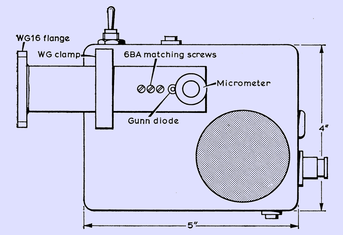
Although a small horn aerial can be soldered to the output end of the oscillator it is a great convenience to use a flange at this point so that different aerials can be coupled up. The waveguide containing the Gunn oscillator is firmly clamped to the outside of the box.
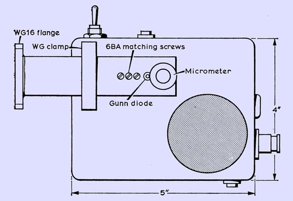
General external view of the 3 cm transceiver. Although three matching screws have been allowed for, only the first has been found to be necessary. The Gunn oscillator supply is fed through the box.
The constructor has the option of using either a positive or a negative earth system. Although not shown in the circuit, a silicon power diode is connected in series with the power supply line and decoupled to protect the circuits in the event of polarity reversal. The crowbar diode and fuse method may be preferred.
Because the IF transformers were salvaged from a defunct FM transistor radio of oriental origin it is not possible to give details. Similar items are available from advertisers; two pairs of single-tuned transformers could be interconnected to do the same job. The overall bandwidth should be 200-250 kHz.
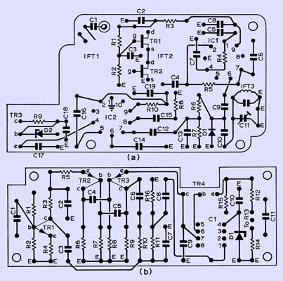
Typical component layouts and wiring: (a) IF/AF board and (b) modulator/PSU board which uses a μA741 in the stabilizer section instead of discrete components. Both boards are wired for negative earth.
The layouts of the printed circuit boards are above. It is not suggested that these component layouts should be followed slavishly by every constructor, but due regard should be paid to the need to avoid RF and AF instability by adopting sensible component layouts throughout. The original box housing the complete transceiver measures 5 by 4 by 1½ in. Operating controls are mounted round the edge.
Alignment
- Check wiring before switching on, set Gunn voltage to 7.5V and, if possible with the use of an oscilloscope, check that there are no parasitic oscillations.
- Presence of tone and modulation can be checked by connecting high-resistance headphones across the 7.5V line. Tone and speech will be faint but audible.
- Check Gunn is oscillating by measuring the current being drawn by it. Set frequency with the use of awavemeter; this will depend in which part of the band one's local activity is. For GMs it is 10,050 MHz. Onepoint to note about the use of the matching screw is that in some cases it has caused a reduction in the tuning range. If this occurs then the matching screw should be removed and the unmatched power level accepted.
- In co-operation with another station, check tone and modulation are working and that deviation is satisfactory.
- Peak IF transformers for maximum audio output. Adjust slope detector for best audio quality on speech.
Operation
Since transmit and receive frequencies are 10.7 MHz apart it is necessary to operate the transceiver in a rather special way.
With the fixed-frequency version the receive frequency must be set up 10.7 MHz from the transmit frequency of the station it is desired to contact. This may be done either by means of a short-range contact with aerials at 900 or by using a common wavemeter. On arrival on-site,fine tuning is accomplished by adjustment of the voltage-setting potentiometer.
When using the tunable model there is no need for preliminary netting. The distant station must be invited over the talk link to transmit first with tone on so that a signal can be received and netted. On changing to transmit the distant station will then receive a signal either 10.7 MHz above or below his transmit frequency. Tone may now be switched off and a voice QSO commenced.
It has been found useful to transmit tone 5-10s at the beginning of each over to allow the receiving station to adjust if necessary for maximum audio output before the speech transmission commences.
Alternatives
The transceiver should work with all Gunn oscillators. The choice of IF is wide open and 10.7 MHz was selected only because components were available. For example, a 30 MHz IF strip was described by G3WDG in the July 1972 issue of Radio Communication. Another option is to use a domestic transistor FM portable as a tunable IF at around 106 MHz with a preamplifier of about 30 dB gain, but IF breakthrough is often a problem due to the un-screened case.
In the tunable version a micrometer is not a pre-requisite. A very satisfactory substitute can be manufactured from ¼ in brass rod and a mounting boss, threaded and tapped respectively to 40 turns per inch. The final ¼ in of the brass rod can be reduced to 1/8 in to reduce the tuning rate. Since the simple self-oscillator/transmitter has been built, several people have constructed the cavity and have found that a nylon screw fitted into the end block makes a good slow-rate tuning screw.
The basic principle used in the transceiver of the self-oscillating mixer can give much better performance if a better IF strip is used. The author is now using an IF strip with two RF stages on 28 MHz, mixer and crystal oscillator, and two IF stages and a CA3089E on 10.7 MHz. Results show that the Gunn compares favourably with the conventional microwave mixer, and unless one is going DX hunting 200 km plus, the simple Gunn set-up can provide a very good 3 cm microwave receiver.
Acknowledgements
The author gratefully acknowledges the help of GM8BKE, GM3DXJ and G3RPE for comments and assistance in the preparation of this article.
|