|
This self-calibrating wavemeter was made in 1975 and the design is accurate to 10 MHz.
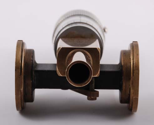
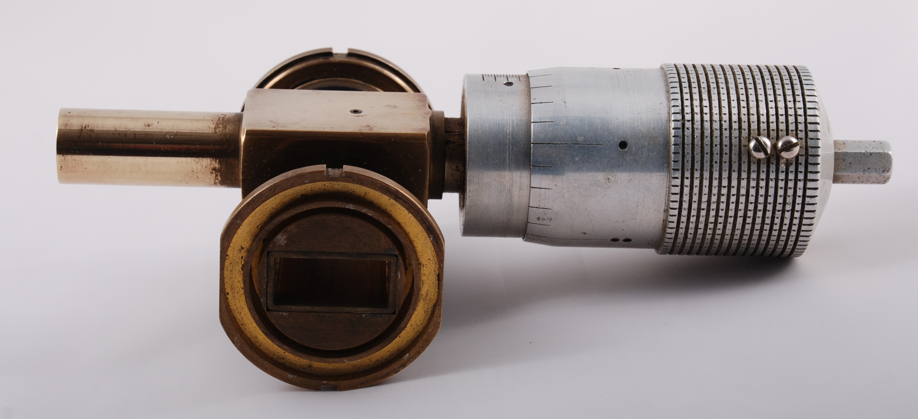
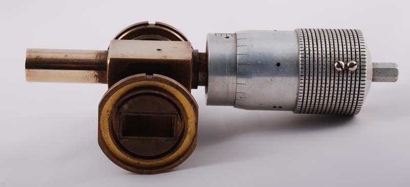
The wavemeter is seen clamped across a piece of waveguide 16
Most current equipment up until the 1990's on 10GHz employed free-running oscillators, the frequency stability of which, although surprisingly good (typically one part in 10,000), nevertheless was poor by crystal-controlled standards. Building a wavemeter actually into the system was not only desirable to ensure operation within the band, but also considerably improved the chances of making contacts.
This wavemeter shown enables frequencies to be measured between at least 9.5 and 11GHz with an accuracy of plus or minus 10MHz. An important feature is that it is self-calibrating, which avoids the need to refer to a precision frequency standard. It consists of a rod of adjustable length set co-axially in a cavity, which is loosely coupled to waveguide forming part of the RF system. Absorption of power occurs when the rod resonates, that is, when the rod is electrically (but not necessarily physically) either λ/4 or 3λ/4 long.
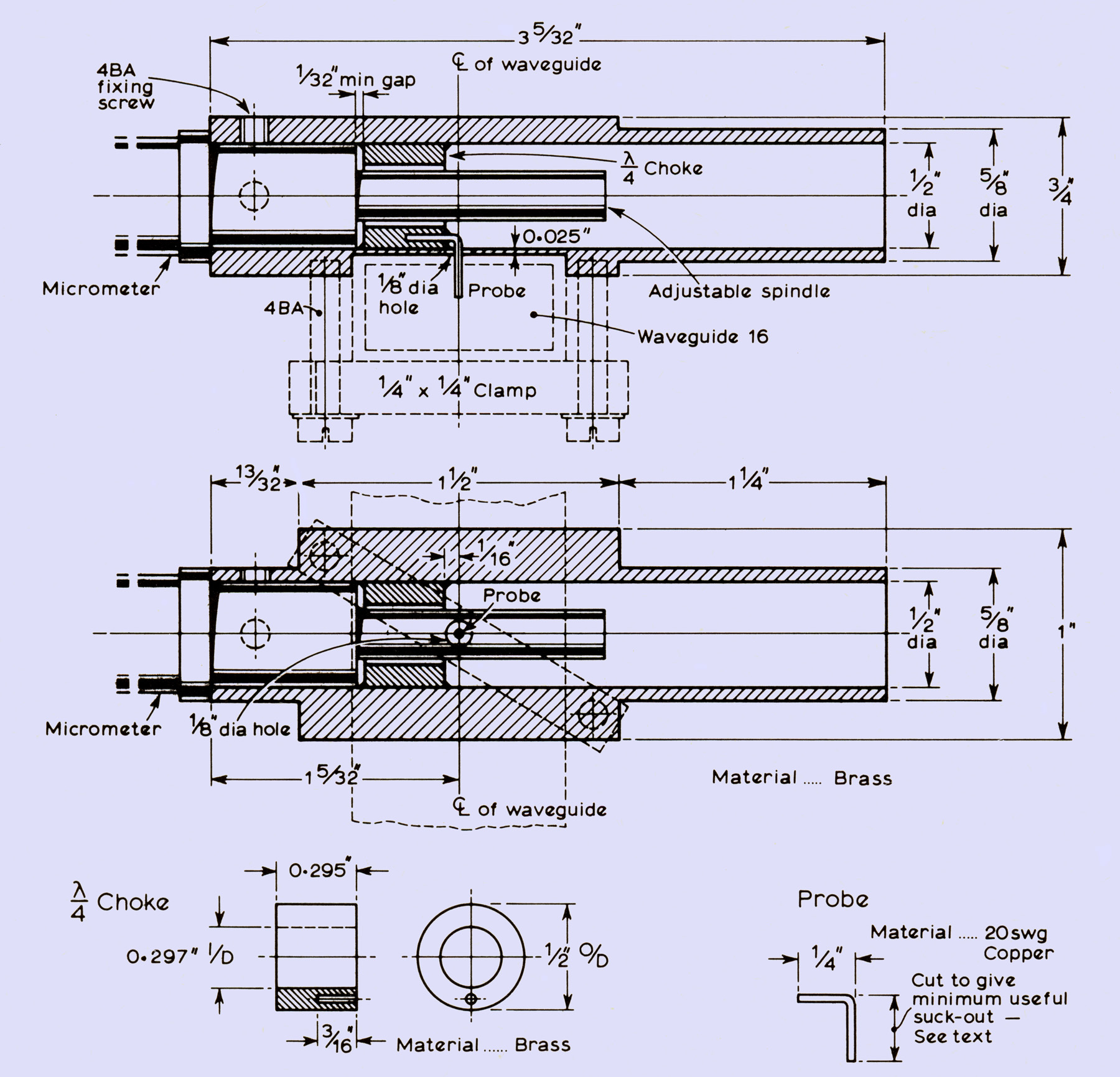
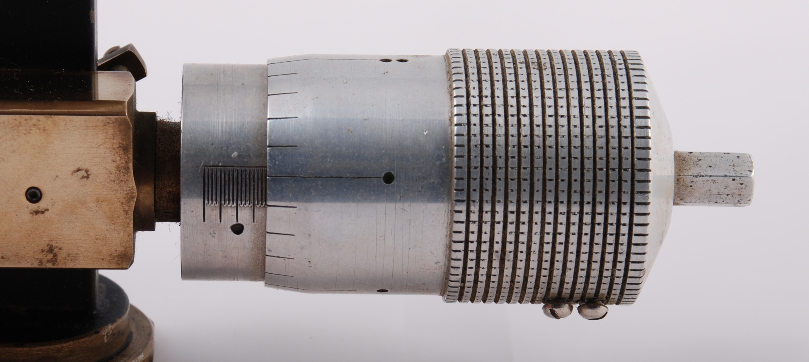
Because the wavelength is short at these frequencies, the tuning rates of this type of wavemeter tend to be high; in the region of 1,300MHz/mm for the λ/4 mode, and 440MHz/mm for the 3 λ/4 mode. The construction problems that could be associated with these rates have been avoided by the use of a micrometer head (The original design published in the RSGB UHF Manual used Moore and Wright type 952M or similar), the spindle of which forms the resonating element. The wavemeter body is fabricated from a block of brass through which a 0.5in diameter hole is drilled. This single hole both locates the micrometer stem and forms the cavity, thus ensuring their alignment. The micrometer spindle passes through a λ/4 choke which defines electrically the position of the 'cold' end of the resonant element more reliably than mechanical contacts such as fingering. To maintain a reasonably high Q, the gap between the spindle and the choke should be kept as small as possible, preferably less than 0.01in, without their actually touching at any point. A short probe from this choke passes through a hole in the thinned wall of the cavity, and through a corresponding hole in the wall of the waveguide, to couple RF.
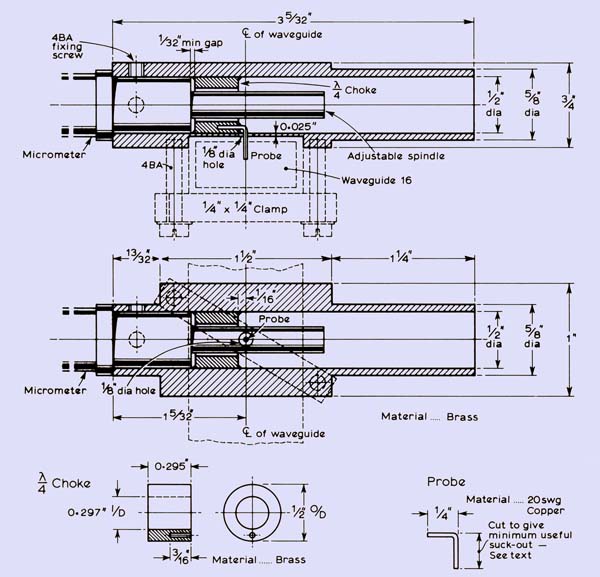
The choke and probe were best soldered in a single operation. The choke is fitted in the micrometer end of the body with the correct orientation, and the probe, formed at the end of a 12in length of wire, is inserted through the wall. The body is then pushed over the plain end of a 0.5in drill held vertically in a vice until the choke is in its correct position, with the probe located in the hole in the choke. The body is clamped using the micrometer fixing screws, and the extended probe wire supported externally. The choke and the probe are then soldered using the minimum amount of solder necessary. The probe is cut to a length of about tin, and the cavity carefully cleaned. The body of the wavemeter and the micrometer spindle may be plated with gold, copper or silver, although this is not really necessary-the plating on the spindle should not exceed 0.0002in or difficulty may be found in re-assembling the micrometer.
To calibrate the wavemeter, a source of RF and a means for detecting relative power levels are required. These will normally be part of the receiver or transmitter with which the wavemeter is to be used. The probe should first be trimmed to reduce the 'suck-out' to the minimum convenient, for example, a 10 per cent reduction in mixer current. For each of a number of (unknown) frequencies the micrometer readings R1 and R2, corresponding to the λ/4 and 3λ/4 suck-outs, should be noted. The difference between these readings is accurately λ/2 at the frequency measured. Hence
f(MHz) = c/2(R1 - R2)
where R1 and R2 are in millimetres and c = 299,600 for air at 25°C and 30 per cent humidity. A conventional calibration curve can be built up in this way for both modes normally advantage should be taken of the slower tuning rate of the 3λ/4 mode.
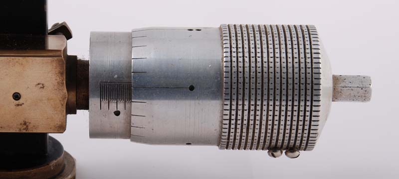
The micrometer head used in this wavemeter was made by Tom Hook and is not a commercial product. This exquisite measuring tool would be a credit to any engineer but knowing it was made by a registered blind engineer who required a watch-makers eyepiece to see his lathe is remarkable. As well as 10GHz measurement equipment Tom also produced items for other bands. See also 24GHz Self Calibrating Wavemeter.
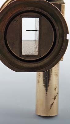
Looking through the waveguide 16 the take-off probe can be seen. The round flanges allow for the rapid coupling into the waveguide circuit with the use of the coupling rings.
|