|
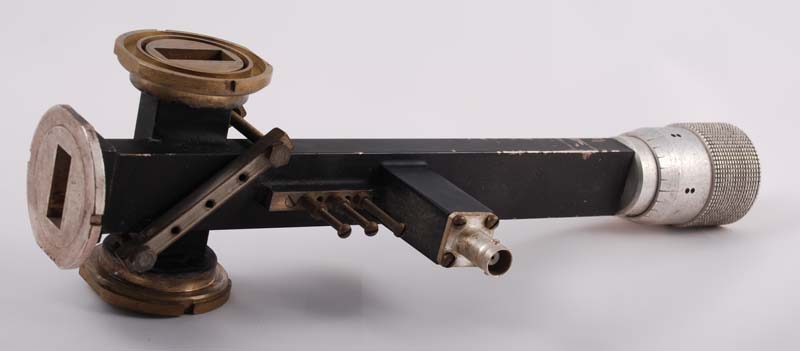
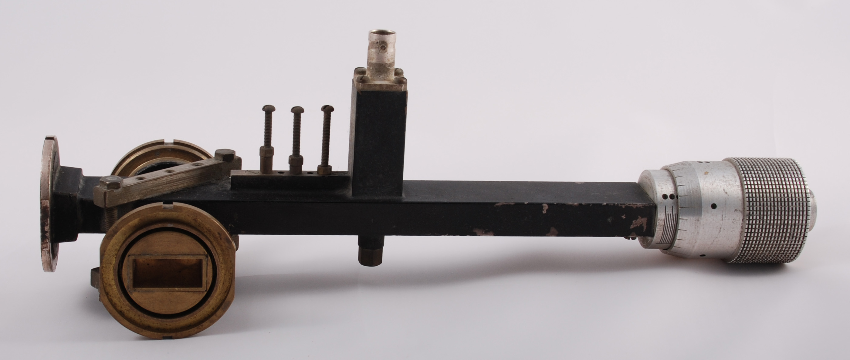
This 10 GHz Gunn oscillator and cross coupler was made in 1975.
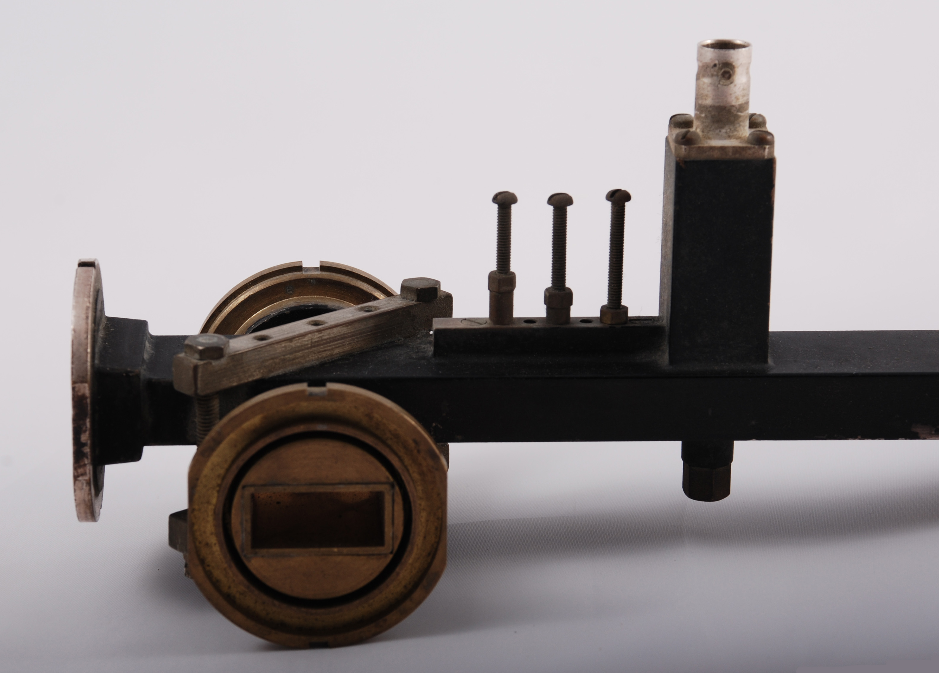
In the picture the clamping of the waveguide 16 for the cross coupler can be easily seen. What is harder to see is that on one section of waveguide the broad face has been removed and the second piece sits in the slot so made. In this way a single thickness of guide wall separates both sections.

The tuning arrangement is by a sliding short across the waveguide that is controlled by the micrometer. Later designs tuned by introducing a dielectric rod or screw into the broad face of the guide.

The Gunn device is contained in the post mounted on the broad face of the waveguide. The underside of the guide has the second mounting for the active device. Power and modulation is coupled to the Gunn device via the BNC connector. Between the Gunn and the flange are a set of matching screws. These are set on a brass bar to give a greater depth of thread for the 6 BA screws. Note the use of locking nuts to prevent movement once aligned.
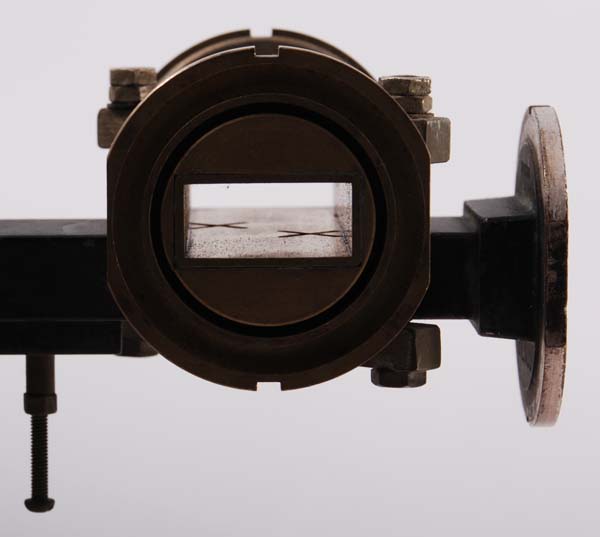
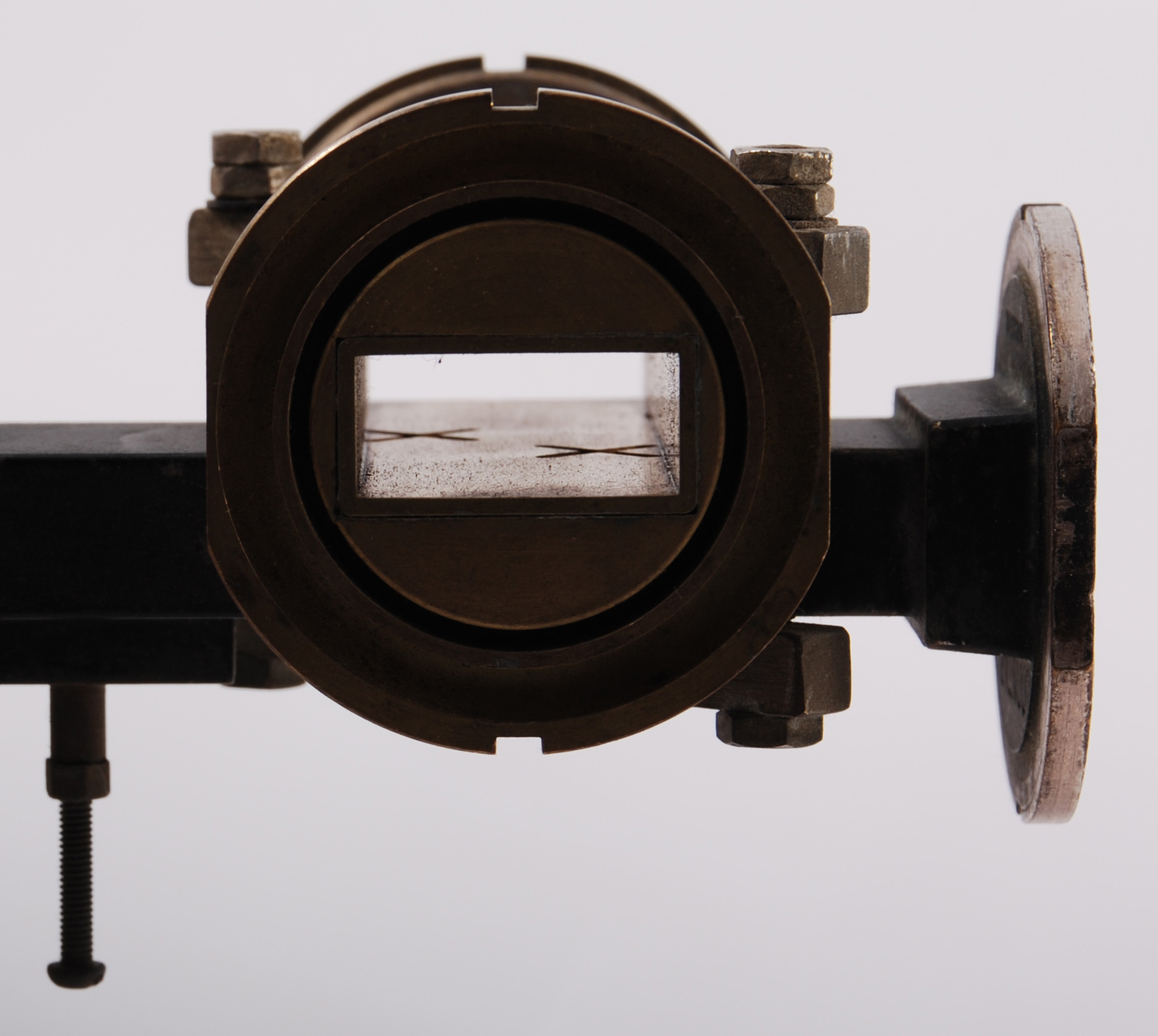
The cross coupler slots can be clearly seen as can the fact that no septum plate has been used. The slots are cut directly into the broad face of the waveguide. This makes machining of the coupler more difficult and shows the skills that Tom had at his disposal.
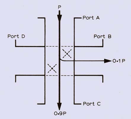
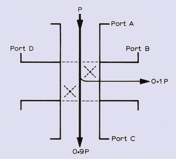
A basic characteristic of a coupler is that it is a reciprocal device. Consider as an example the cross coupler illustrated. If a power P is applied to port A, then 0.9P will appear at port C, and 0.1 P will appear at port B. If the coupler is well made, negligible power will be coupled to port D. If the same power is applied to port D, then 0.9P will appear at port B, 0.1P at port C and none at port A, and so on. Thus, by the appropriate choice of ports, two signals can be combined with a controlled degree of coupling. In simple terms the use of a coupler enables the correct driving of a mixer diode whilst obtaining the maximum output to a transmitter port.
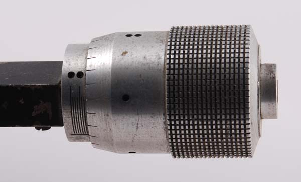
As with his other equipment Tom Hook made the micrometer head himself. Due to restricted sight he marked the micrometer divisions with coloured dots. The colour code he followed was the standard colours for resistor markings.
|