|
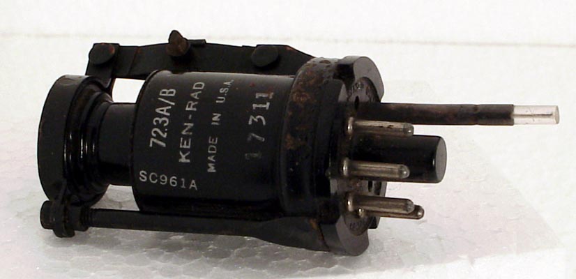
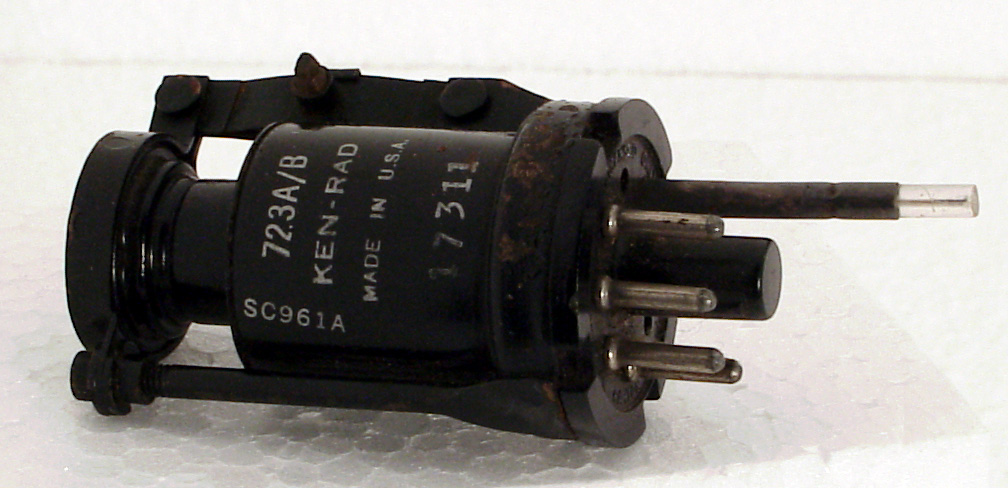
The 723A/B Klystron was designed for microwave RF generation of about 20 mW at 9.7 GHz. It produces a continuous output and can be modulated for communications use. The output power is taken from the probe by passing the tip into waveguide. The base for this valve is special but an International Octal holder with pin four drilled out is equivalent.
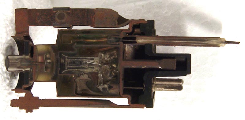
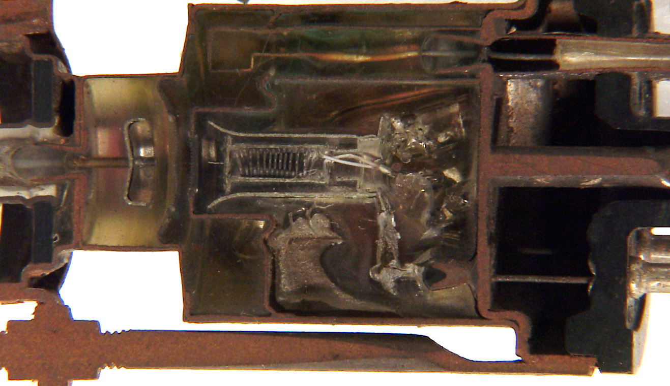
The sectional view show's the cavity on the left with the probe at the top. The probe is 31 mm long and metal cased for 23 mm.
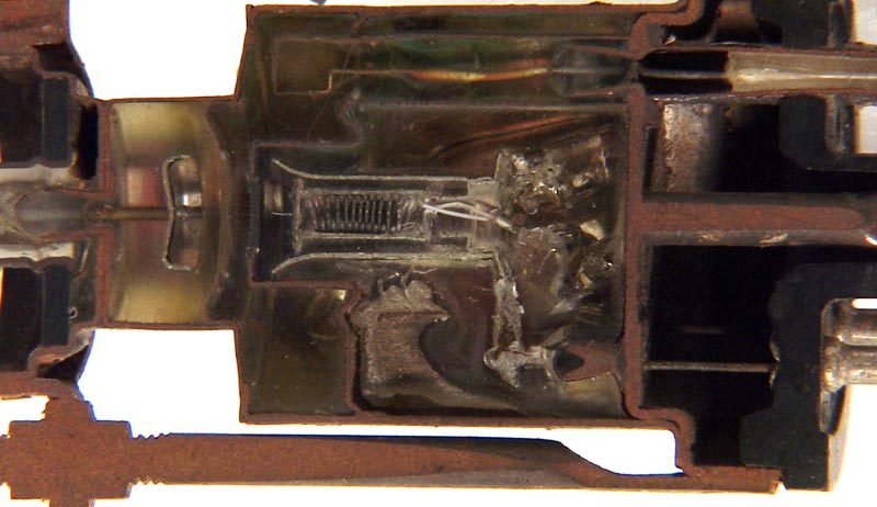
In this close-up sectional view the spiral heater can clearly be seen inside the cathode cylinder. The main emitting surface is the flat circular plate. The cavity contains a hairpin pick-up loop, and this can be seen exiting as the probe. The top-cap leads to a stout rod, and in turn leads to the concave top of the cavity. This is the element that is moved by the adjusting screw.
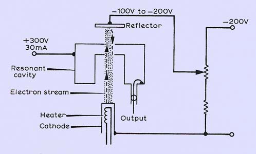
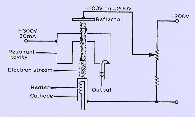
This diagram shows the components of the klystron in outline view and can be directly related to the physical structures seen above.
The thin metal tube envelope is 25 mm in diameter and, excluding the IO base pins, is 56 mm tall.
|