|

Cross Channel Microwaves 1934 Style
Additional note. The first cross channel microwave QSO took place on 31 March 1931 between the Dover and Calais areas. The experiment was conducted by engineers from ITT laboratories in Britian and France on a frequency of 1.67 GHz with dishes of 3 M diameter.
From a radio amateur viewpoint the microwave scene appears to be a pretty modern phenomenon. Despite the efforts of pioneers like, say, GSRZ during the 1950s, amateur activity in the microwave bands (23cm and higher) seems to be a speciality mode which has only just caught on. While this is not strictly accurate it is certainly true that recent developments such as low noise GaAs FETs at affordable prices, micro-stripline circuit techniques and the availability of commercial equipment have made microwave operation a lot more fun. Gone is the need to be an expert in 'plumbing' or at recognising exotic pieces of military surplus gear to get on the air. In short, the technology has become a lot more comprehensible and within the reach of the average amateur.
In the light of this, the problems which faced pre-war experimenters in microwaves look even more formidable. Despite this over fifty years ago the two sides of the English Channel were linked on 17 cm with just half a watt of RF power. Three years later, in 1934, a full commercial service was in operation. The story of this world first is an unusual and interesting one, which has been somewhat obscured in the mists of time.
The instigator was a certain Colonel Sosthenes Behn, president of the International Telephone and Telegraph Corporation (ITT), who in 1927 decided to set up a R & D laboratory in Paris. Flamboyant character that he was, he demanded positive results quickly - the exact field was not important so long as the results were spectacular! Radio clearly had a promising future so it was decided to exploit the extremely short wave region, then unexplored territory. Plans were quickly made: radio energy would be produced at wavelengths around 17 cm and concentrated in sharp beams by means of parabolic reflectors. Calculations indicated it ought to be possible to cross the English Channel at its narrowest point, using almost the same route as Bleriot did when he was the first to cross the Channel by aeroplane in 1909.
In charge of the project was Andre Clavier and by 1931 his team had brought the concept to reality and was ready to make the first public presentation. A large gathering of officials from the British and French post offices, scientists, military experts and pressmen attended a demonstration of microwave telephony which was 100 percent successful. The news had wide coverage in the press and ITT's London publicity man, McGrath, coined the term 'microwave' to give the transmissions a catchy name and capture popular appeal. ITT quickly realised the potential of the technique, describing in a technical paper the project of a microwave link from London to Paris using repeaters 50 km apart. The technicians also observed that ships crossing the beam, which in the middle of the Channel ran close to the water, interfered with the transmission and the size of the ship could be established. The significance of this early experiment in radiolocation was not, however, realised at the time.
Line of sight
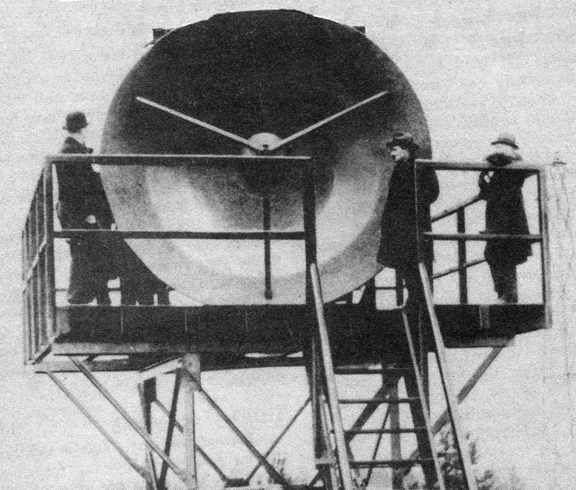
The air ministries in Britain and France were sufficiently impressed to order a commercial system to link airfields on either side of the Channel at Lympne (near Folkestone) and St. Inglevert (near Boulogne) and this was put into use in 1934. The length of this link was 56 km, the frequencies used - 1724 and 1764 MHz (17.0 and 17.4cm) - and the transmitter power was 0.5 watt. Line of sight operation was assured by locating the aerial parabolas on high towers (see photo). The diameter of the paraboloid reflector was lO ft 6in, having again of 28 dBd. A hemispherical reflector at the focal point added an extra 5 dB. Separate TX and RX dishes with frequency separation were used initially to allow simultaneous duplex operation. Later on a single reflector was used, with outward and inward transmissions cross polarised at right angles to each other. The link was used for both speech and teleprinter (RTTY) signals. Special triodes known as 'micro-radions' were used and these were made to oscillate by reversing the usual potentials On grid and anode. The normal control function of the grid was not used and there was no anode current. Other details will be apparent in the diagram. And that, in a nutshell was the world's first commercial microwave radio service. When it ceased I have been unable to find out, and any further details readers may be able to supply will be most welcome.
The following is the actual text from an article that first appeared in The Electrical Review February 2nd 1934
Micro-ray Telephony
Power of the order of 0.5 W is radiated from aerials less than an inch long on a wavelength of 17 cm. (claimed to be the shortest so far used commercially), as compared with 900 m. for civil air traffic and 1,300m. for route traffic messages. The wavelength used for reception is 0.5 cm longer than that used for transmission, which slight 'stagger' permits duplex working by telephone and 'Creed' teleprinter. Hitherto wireless tele-printing has been done experimentally only, owing to the difficulty of obtaining a radio signal of constant strength and free from interference The micro-ray system overcomes this handicap and messages will be transmitted at a speed of sixty to seventy words per minute.
The distance between the two terminals is 56 km. and the path between them is clear of obstacles, the electro-optical equipment being installed on the roof of a hanger 43 ft. above ground at Lympne, and on 66-ft. steel towels which have been erected at St. Inglevert.
For generating the oscillations at the rate of 1,700 millions per second use is made of a specially designed micro-radion valve, fitted with a double-ended helical grid and a normal cylindrical plate electrode. The double-ended grid, in addition to being biased positively, is included as a tuning element in the main oscillatory circuit. The actual wavelength is a function of valve geometry, output circuit, and electrode voltages; the latter are therefore the tuning elements. The normal control function of the grid is not used; it is the 'oscillating electrode', while the 'plate' is the 'reflecting electrode'. The latter is biased negatively, and there is no plate current; the grid is biased positively, and in many respects replaces the anode of a normal valve. For example, the grid dissipates the power lost in the valve. The filament is of tungsten, and is operated at a temperature giving voltage saturation of the space current with respect to the oscillating electrode.
Electro-optical Systems
The main reflector is paraboloidal, 10 ft 6 in. in diameter, and is spun out of an aluminium sheet about 5 mm. thick. A spherical reflector, three wavelengths in diameter, faces the large reflector, to which it is attached by three radial wooden members. The antenna, of the half-wavelength type, is placed at the focus of the paraboloidal reflector, which coincides with the centre of the spherical reflector.
The focus of the paraboloidal reflector is situated in the aperture plane of the spherical reflector, and the radiation emitted from the antenna on the transmitting, side is concentrated into a very sharp beam by means of the main paraboloidal reflector. The spherical reflector is used to reflect the direct forward radiation of the antenna back to the paraboloidal reflector, thus increasing the gain of the total electro-optical system. The gain of the paraboloidal reflector alone is of the order of 28 decibels, which rises to31 decibels when the spherical reflector is added to the system. The same gain is obtained on the receiving side.
The antenna is fed by a concentric transmission line, the external surface of the outer tube being tapered, and of great rigidity to prevent antenna movement on windy days. The inner member is insulated by 'Micalex' spacers located at the voltage nodes the purpose being to keep the loss as low as possible.
Behind the large reflector the valve is mounted in a socket of the conventional bayonet pattern, but the two lead-in wires to the oscillating grid electrode of the valve are adjustable in relation to the transmitting line in order to tune the oscillatory circuit of the micro-radion valve on site. The length of the tubular transmission line is made equal to three-fourths of the wavelength used, to match the impedance of the antenna to the internal impedance of the valve, and thus give optimum working conditions. Adjustment of the tube is by a screw and small hand-wheel. All surfaces conducting high-frequency currents are gilded by a galvanic process to prevent corrosion. Other metallic parts are painted.
On the transmission side, the auxiliary transmission line is connected to a thermocouple, and an associated galvanometer in the control room acts as a radiation indicator.
Apart from the adjustment of the oscillatory circuit and transmission line, which does not have to be changed except in the event of the valve burning out, all control adjustments are located in the control room on a number of panels mounted on two vertical bays.
Potentiometers control the voltages applied, and modulation, which may be speech or 3,500 cycle signals coming from the teleprinter unit, is increased in amplitude by means of two amplifiers. The first is an ordinary transformer-coupled two-valve amplifier of the repeater type with attenuators for gain control, and the other is a push-pull output stage employing three valves. Signals coming from the amplifiers are applied to a voltage divider which supplies the modulation to the electrodes of the micro-radion valve in a suitable ratio.
Incoming signals are picked up by a receiving reflector, focused on the receiving antenna, and demodulated by means of the micro-radion valve. To stabilise the demodulation process an auxiliary oscillator applies a 500 kHz voltage to both electrodes of the receiving valve in a different ratio, which is determined from the constant frequency curve of the valve in the same way as the corresponding ratio for the modulation on the transmitting side.
It is stated that this method renders the adjustment of the system much less critical in operation. The demodulated signal is then fed into a receiver amplifier and gain control panel and passes into an ordinary telephone receiver, or is transmitted to the teleprinter equipment for a second demodulation used in conjunction with a single-current voice-frequency equipment.
The signal distortion is very small, and the circuit includes a device to maintain the detected current approximately constant over a wide variation of signal strength, since the teleprinters operate on the start-stop principle, there is no need to synchronise the transmitting and receiving machines. Further, the operation of the voice frequency unit and the radio system is simplified by reason of the fact that the speed of the signals sent out are independent of the rate of striking the teleprinter keys.
|