|
With the ready availability of doppler modules intended for use as intruder alarms and radar speed detectors, more and more amateurs are beginning to experiment with microwaves. Although these modules offer the nearest thing to a 'no plumbing' rig, they do nevertheless present one problem, namely retuning to operate within the nearest amateur band. At this point, having studied some excellent wavemeter designs in such publications as the VHF/UHF Manual, the would-be microwave experimenter in all probability gives up and reverts to 432 MHz or lower. The reason is that, if ready-made doppler units avoid the need for plumbing the same is definitely not true of accurate wavemeters.
Fortunately the very design of doppler modules, coupled with the properties of microwaves themselves, leads to a very simple method of getting equipment at least roughly on the desired frequency.
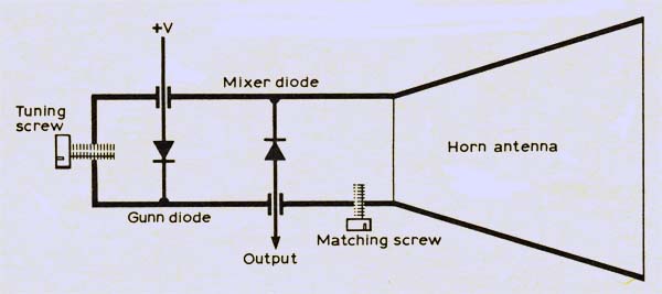
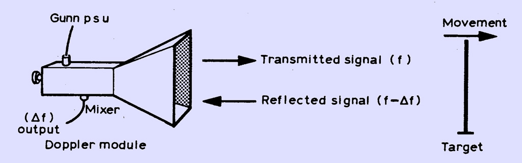
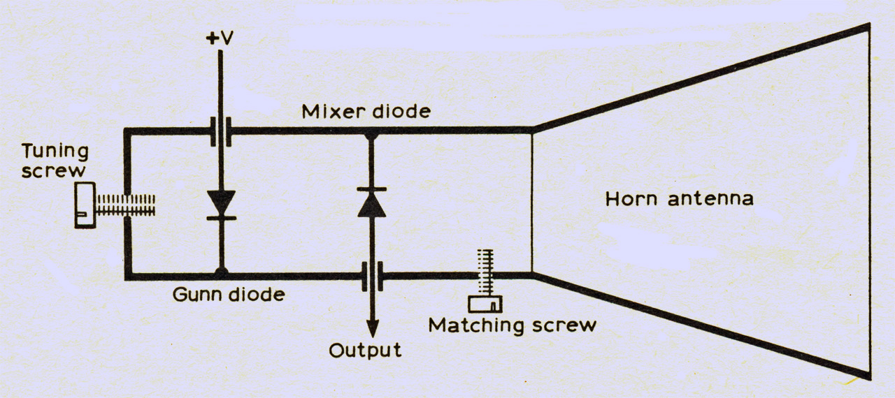
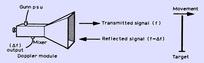
The figure above shows the general layout of a typical unit, together with the sort of 10-15 dB gain horn antenna that is often supplied to match. (Other types of doppler module have the Gunn diode and the mixer diode in separate pieces of waveguide mounted back-to-back; the operating principle is, however, identical.) See The Wessex Modules.
Detecting Movement
In normal use the microwave energy generated by the Gunn diode serves two functions: the first of these is to transmit a beam at the target, and the second is to act as a local oscillator. If the target (such as your car!) is moving, then it will reflect the beam back to the unit with a frequency shift corresponding to the speed and direction of motion. The diode serves to mix this returned frequency with the generated frequency and produce an audio output accordingly (top picture).
For amateur transmission purposes the external circuitry is somewhat different, and several good arrangements have been published from time to time in RadCom. To begin with, the Gunn diode will be modulated with audio frequencies to enable voice transmission to take place. Similarly the mixer diode, instead of producing a DC output directly, will drive a conventional IF strip operating anywhere between 10.7 and l00 MHz. Almost certainly there will also be a meter to monitor the mixer diode current, this being the only essential ingredient of the following method of measuring frequency.
Reverting to the top picture, it is easy to deduce that the mixer diode output, when used as a doppler radar, is dependent not only on the target speed but also on the transmission frequency. Assume for a moment that the target is an integral number of half-wavelengths from the unit. Under these conditions the reflected signal will be in phase with the generator, and the mixer current will be a maximum. If the target is then moved λ/4 further away, the total signal path will be λ/2 longer, with the result that the reflected signal is out of phase. The mixer current will now be at a minimum. If the mixer current is monitored while a target slowly recedes or approaches, it will be seen to rise and fall once for every λ/2 the target moves. (This means, other things being equal, that the higher the Gunn frequency the more sensitive the unit is for speed or distance measurement purposes.)
Frequency Measurement
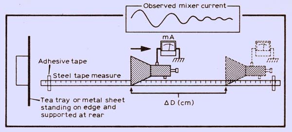
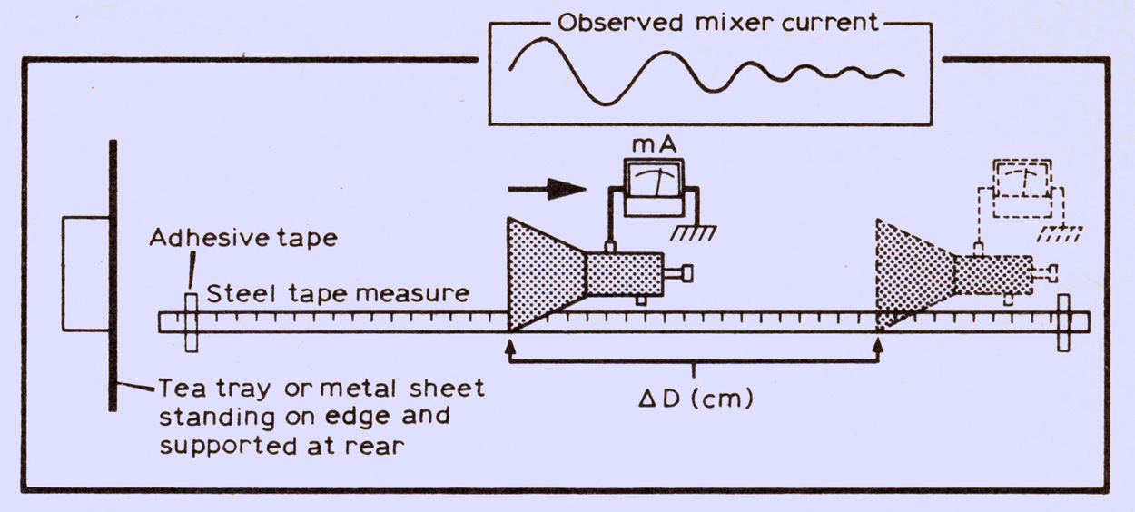
For amateur frequency measurement, this principle can be directly applied at the kitchen table level. For a typical doppler module, enough signal is reflected from an ordinary metal tea tray 10 ft away to be readable on a mixer current meter. Apart from the tea tray, all that is then needed is a metal tape measure and some adhesive tape. The general arrangement can be seen above. First, make a scribed mark at some convenient point on the Doppler module (or its casing) adjacent to the metal rule. Then stand the tea tray on its end about 2 ft in front of the module, though the precise angle and distance do not matter as long as the tray does not move relative to the rule.
Next, move the doppler unit backwards or forwards until the meter shows a maximum. (Such maxima will occur every 1.5 cm for a 10 GHz rig). Choose one such maximum and note carefully the measurement on the rule corresponding to the scribed mark on the equipment. If the module is then slowly moved away from the tray, the mixer current will fall and rise in successive cycles. In theory one could measure the distance moved in just one cycle, but the accuracy would be too low for practical purposes. It is therefore best to measure the distance over which the mixer current has gone through 20 or more cycles. (How many depends entirely on the length of the kitchen table and the strength of the reflected signal. When the distance is too great the meter movements are too small to read accurately.) To calculate the frequency, remember that any movement of the module must be doubled to get the change of path length. The relationship is as follows:
Frequency = (Velocity of EMR in free space x No of measured cycles) / 2 x measured distance
Simplifying and putting in practical units, this becomes:
Frequency (GHz) = (14.99 x N) / ΔD
where N = number of cycles and ΔD = measured distance.
To take a practical example: suppose that 40 cycles were measured over a distance of 59 cm. Inserting the data into the equation:
F = (14.99 x 40) / 59 = 10.16GHz
The accuracy of this method is determined largely by the accuracy of measurement. In the above example assume that the 59 cm were measured to an accuracy of 1 mm; not too difficult in practice. The accuracy would then be approximately one part in 600, ie within 17 MHz at 10 GHz.
One other possible source of inaccuracy is the effect on the Gunn oscillator stability of too much signal being reflected back into the horn. For this reason the tea tray should be kept at least 1ft from the module, and preferably more. It should also be borne in mind that if the module is fitted to any other antenna or waveguide system, the change of loading could also alter the frequency. Nevertheless, for getting a simple microwave rig roughly on frequency and safely within the allocated band, there can scarcely be a simpler method.
Warning
Although the level of microwave radiation from equipment of this nature is extremely low, there are circumstances in which particularly sensitive parts of the body can be exposed to excessive amounts. The eyes are especially vulnerable in this respect, and experimenters are warned NOT TO LOOK DOWN THE END OF A WAVEGUIDE with the equipment switched on.
Acknowledgement
The author gratefully acknowledges the assistance of Richard Lambley, G8LAM, in the preparation of this article.
|