|
This article describes Bandpass filters made in WG16. In RadCom, January 1979 the full, and now classic, JVL transverter design appeared.
These filters for 10 GHz have 3 dB bandwidths of 20 or 60 MHz, as is shown by the measured response curves given below. G3JVL, who designed the filters, uses the former in the local oscillator chain of a receiver to reduce the noise generated at signal frequency which would otherwise degrade the receiver performance.
Even if a relatively low IF is used, significant rejection of noise can be obtained; for example, at 30 MHz the rejection is 27 dB. The 60 MHz bandwidth filter is used to eliminate effectively the second channel response of the receiver.
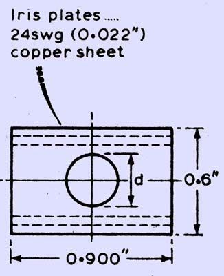
As is shown above, the filter consists of a length of waveguide 16 in which iris plates are used to define three resonant cavities which are coupled by centrally placed holes of specified dimensions. The basic design frequency is 10.5 GHz, but the tuning screws fitted may be used to tune the filters down to 9.SGHz at least. Matching screws are fitted at each end of the filter as necessary to tune out any mismatch with the external circuitry.
In order to maintain the Q of the filter, it should preferably be made entirely from copper. Brass should only be used if it can be copper- or silver-plated. after assembly. The tuning screws can be of brass only if little of each projects into the cavities, otherwise threaded copper rods should be used. The matching screws can be of brass, or even cadmium-plated steel if little projects into the guide.
The filter can be constructed as follows:
- Scribe deeply into the top and bottom broad faces of the guide grooves corresponding to the position of the irises.
- Using a fine saw such as a junior hack-saw blade, first cut slots at each corner and then use these as a guide to extend the cuts across the full width of the top and bottom walls of the waveguide.
- Fit the iris plates in their correct positions, and fix them in place. by bending the corners of the iris plates. Jig the tuning and matching screw bearing nuts (if fitted) using chromium-plated screws. Fit any flanges required and solder all joints in a single operation using a small gas flame. Alternatively, solder only the joints on the underside of the filter, invert it and solder the second set while the first is cooled by small pieces of tissue soaked in water. This technique prevents any solder entering the cavities, which would reduce their Q. It is safer to use plain solder with a flux that can be washed away (eg Baker's Fluid) rather than to risk organic residues being left behind.
The following figures are for 3 dB bandwidth and corresponding dimensions in mm.
60 MHz bandwidth - X = 17.8, Y = 18.2, d1 = 9.0, d2 = 4.3
20 MHx bandwidth - X = 18.2, Y = 18.7, d1 = 6.2, d2 = 2.95
|