|
Prompted by readers' reactions to the advertising of 'surplus' Gunn diodes in recent editions of Radio Communication, the writer offers his initial experiences in using similar devices.
Gunn diodes (or more precisely Gunn devices since they have no rectifying characteristics) consist of a thin layer of gallium arsenide (10 μm for a 10 GHz device) to which are connected appropriate electrodes. The application of about 7 V of the correct polarity causes a direct current to flow, typically 120 to 150 mA, superimposed on which are current spikes occurring at intervals of about 10*-10 S. If such a device is fitted into a cavity resonant at about 10 GHz, then useful amounts of RF will be generated continuously: for small devices the output is between 5 and 20 mW. These power levels are similar to those obtained from small klystrons in current use, which require a much more elaborate power supply.
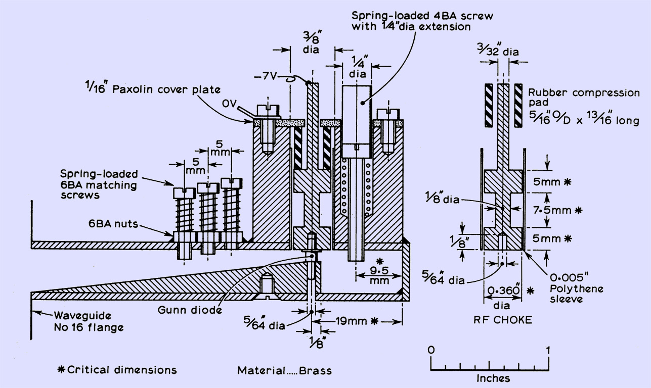
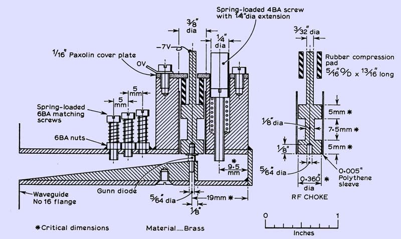
The most effective cavity investigated by the author is shown in the figure. It consists of a length of waveguide 16 (0.9 in by 0.4 in inside dimensions), closed at one end and fitted with a flange at the other. A block at the closed end contains the RF choke associated with the DC feed, and supports the tuning mechanism, a 4 BA screw. The diode is mounted across the narrow width of the waveguide at a distance of 19 mm from the closed end, which corresponds approximately to λ/2 in waveguide. Note that λ in waveguide (λg) is 3.97 cm not 3.00 cm as in air. The diode is mounted on a wedge 0.9 in wide in an attempt to improve matching. The length of the wedge is not critical but preferably greater than 3λg/2. The DC feed to the diode is via an RF choke which consists of two sections λ/4 long in polythene separated by a thin section λ/4 long in air: in HF terms this choke could be thought to consist of a low-inductance high-capacitance section, a high-inductance low-capacitance section, followed by a low-inductance high-capacitance section, ie a conventional π-filter broadly tuned to 10 GHz. The diode is held in place by slight pressure exerted by a short length of rubber tubing which also helps to absorb any RF leaking past the RF choke. Three 6 BA screws spaced λg/8 apart are set into the waveguide to provide a better match to the output port. These should be mounted as near to the diode as convenient.
Fabrication is simplified by brazing on the end plate. If the wedge is located by a 5/64 in drill and clamped (to stop it floating on solder), the block located by a 3/8 in drill, and the 6 BA nuts held in place by chrome-plated screws, then they may be soldered in one operation without difficulty. The power supply required may be zener-controlled or preferably a simple variable stabilized supply. The voltage regulation required is not critical as frequency dependence is roughly 10 MHz/V.
In setting up the original units, the oscillator was connected via a 10 dB attenuator into a diode mixer fitted with a wavemeter. By trial and error the matching screws and battery voltage were adjusted to give the best compromise between power output, immediate starting of oscillation and the range of tuning required. The minimum penetration of matching and tuning screws was aimed for. On any particular frequency stability was of a high order: the drift on switching on was not detected on a wavemeter having a resolution of 1 MHz. This compares with the drift of 10 to 20 MHz observed in switching on small klystrons also used by the writer. The several diodes tested in four similar cavities all showed a common defect in performance. When operated into other than a well-matched broadband load, there was a tendency to frequency 'hop' by typically 10 to 50 MHz when a small change was made at critical points in the settings of the tuning screw, the matching screws, or the voltage applied to the diode. When operated into a matched load, these problems virtually disappeared and reliable tuning over a range of 100 to 200 MHz was obtained. When used as the local oscillator of a receiver, good matching can easily be achieved, since only a small proportion of the power generated (5 to 20 mW) is required to operate the mixer (0.5 to 1 mW), the rest being dissipated in a matched load. The oscillator may feed the mixer either through a 10 to 15 dB attenuator, or via a directional coupler into a dummy load.
This dependence of frequency on load makes the application of Gunn diodes to transmitters rather more difficult. Thus, when connected to a dish and feed of moderate match (vswr 1.5:1), quite erratic results were obtained. Even when connected directly to a well-matched horn, it was found difficult to tune reliably over more than 10 to 20 MHz: while usable with care, such transmitters could not be used with the confidence with which one likes to operate transmitters. For those interested in experimenting with these devices, a useful initial guide using the Mullard CXY11 series of devices is A Gunn device transmitter (10 GHz), which may be obtained from Educational Services, Mullard Ltd, Mullard House, Torrington Place, London, WC1.
|