|
This article is an edited version of part 13 of a series.
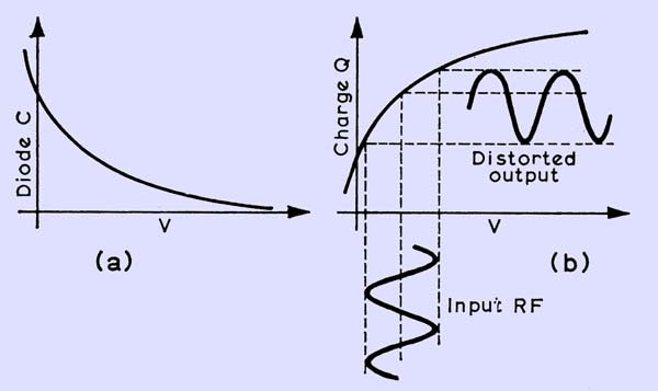
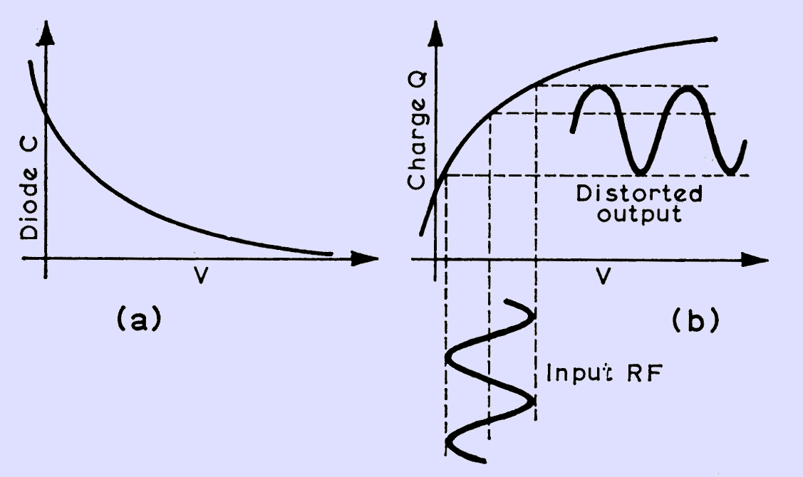
(a) Capacitance and (b) charge variation against bias on diode. Note the distorted output in (b).
The curves for a capacitor are all markedly non-linear and this property can be used as an element in a circuit to modulate, demodulate and multiply frequency. This is non-linear reactance, rather than a resistance, however, and because of this, very little loss occurs.
The charge in a capacitor is equal to the capacitance multiplied by the voltage across the capacitor: Q = CV, and the capacitance/voltage curves above approximate very roughly to the reciprocal of the square root of the applied voltage. Combining Q = CV and C approx l/V*0.5, the charge on the capacitor can be seen to be proportional to the square root of the voltage. If an RF voltage is applied to a capacitative reactance which behaves in this manner, a heavily distorted charge, consisting mainly of the second harmonic of the input, is produced and can be tapped off using a tuned circuit. A diode used this way is called a varactor diode. This action can easily be demonstrated by using a zener diode as the non-linear element and a signal generator tuned to about 500 kHz giving an output of about 0.25 to 0.5V rms.
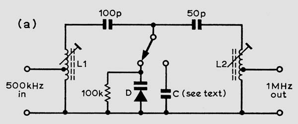
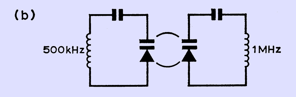
Circuit for demonstrating non-linear reactance effects.
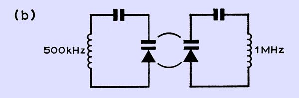
The circuit broken down into its basic components.
In diagrams (a) and (b) above the circuit is in two halves: the left-hand part is tuned to 500 kHz and the right-hand part to 1 MHz. RF current is passed through the diode at 500 kHz and, due to the non-linear reactance of the diode, a proportion of its second harmonic will (or should be) circulating in the right-hand part of the circuit. L1 and L2 are IF transformer coils: L1 could be two coils in series (aiding), tuned to resonate at 500kHz with the diode in circuit, and L2 one coil tuned to resonate at 1 MHz. Resonance can be measured across the complete coil with a low-capacitance, high-impedance RF probe. Having tuned each circuit, apply 500 kHz to L1 and measure the output across L2. Tune this coil up very carefully (the resonance peak is very sharp). To prove this frequency has been produced by the diode and is not just generator harmonics slipping through, apply 1 MHz from the generator to L1 and see how much of this gets through to the output. With any reasonable Q in the coils, it will not be very much. Another proof would be to replace the diode with an equivalent capacitance; the output will go down to a very low proportion of the previous value.
Other harmonics can be produced in a similar way. The second harmonic can mix with the fundamental and produce the third, and the second can produce its own distorted charge for the fourth harmonic, although the output of the fourth harmonic is improved if the third is produced as well. In all these circuits for multipliers, current must be allowed to circulate through the diode at all the respective frequencies by circuits that are tuned to those frequencies. These circuits, excepting the output circuit, are called idlers. All tuned circuits have to be of the maximum unloaded Q to minimize circuit loss and they can be considered either as parallel- or series-tuned, depending on which way one looks at them.
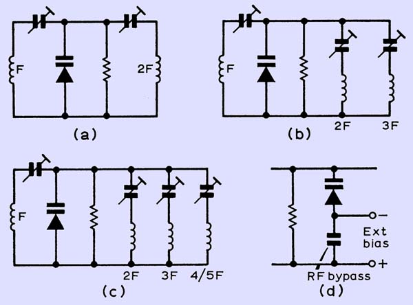
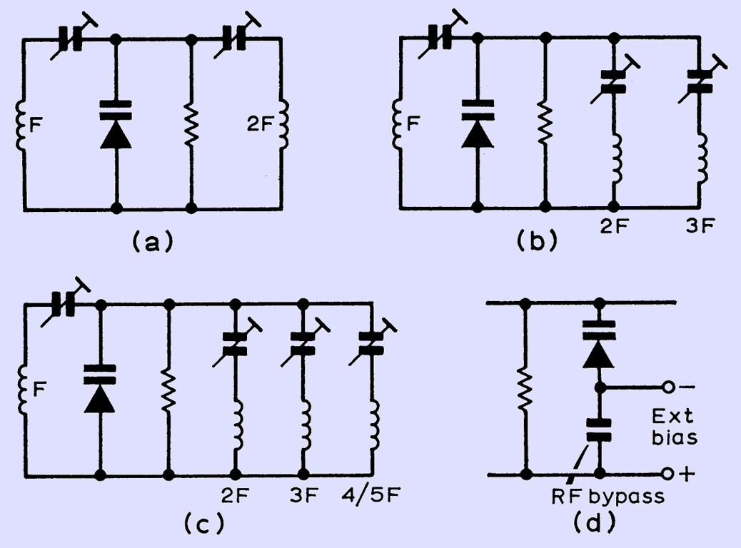
Various varactor multipliers: doubling in (a), tripling in (b) and quadrupling or quintupling in (c). (d) shows a way of altering the bias to make the input RF lie along some other point of the curve and possibly to improve the effect.
The diode average capacitance (at a certain voltage) is in series with the tuning capacitance and both of these tune the coil. A properly-designed doubler of this kind, using a diode specifically meant for this function, can give an output of about 90 per cent of the input, the rest being dissipated in circuit resistances. When multipliers of this sort were first used, some surprise was expressed that they could be fed with an AM input. This cannot normally be done with a frequency multiplier, at least to get a coherent output, but it seems that a non-linear reactance can demodulate at the input frequency and remodulate at the output frequency (with a little added harmonic distortion), to give an output which is at least intelligible.
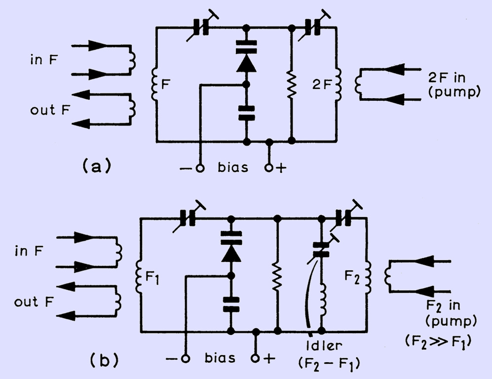
Another use for varactor or charge-storage diodes is in, parametric amplification. If a certain charge is fed into the diode capacitance at the crest of an RF half-cycle and then the capacitance is suddenly decreased, the voltage associated with this charge becomes larger: Q = CV. With C reduced to half its original value, the voltage would double for the same charge. The potential energy of this charge, which is equivalent to ½CV*2, would double as well. Obviously this would need some form of outside energy to make up the difference. If the capacitance is suddenly returned to its original value when the RF voltage becomes zero between its positive and negative half-cycles, no additional energy is needed because the PD across the capacitor is zero. Some energy has to be supplied to the circuit twice every cycle: RF energy at double the frequency. This RF energy, which is called the pump frequency energy, must also be in phase with the original frequency wave crests. Part of this pump frequency energy is transferred to the original frequency and amplifies it. The processs is called parametric amplification. As it stands, it would be quite difficult to carry out in practice because of the necessary phase relationship, but this relationship can be obtained simply by letting the pump frequency beat with the original frequency and providing an idler circuit for the beat frequency to circulate as is shown below.
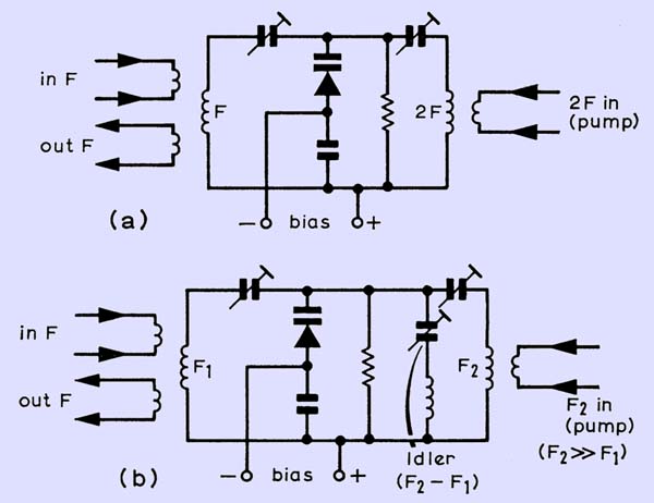
(a) Basic series-tunes parametric amplifier. (b) Parametric amplifier with idler.
Of course, the idler circuit can provide a useful output of the difference frequency as a mixer, but care needs to be taken not to load the circuit too heavily. This method of amplification or mixing can, if done carefully, provide a really worthwhile gain and considerably less noise than most other methods but, as with all amplifiers, the parametric system can be considered to show negative resistance and can readily oscillate at the input or idler frequencies if given a chance: eg when the tuned circuit and diode losses are canceled by this negative resistance. It thus seems to be a matter of balancing Q values in the various circuits against each other to get the best results.
This negative resistance and amplification mentioned above has been obtained through energy supplied from an outside RF source.
|