|
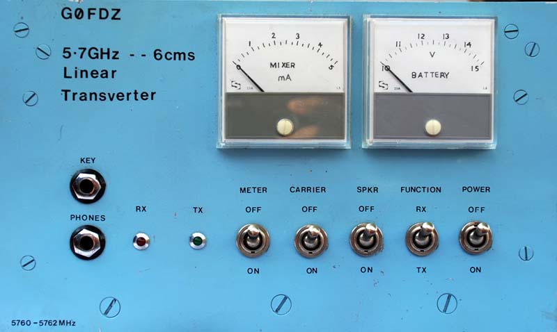
This magnificent and large piece of equipment was made in the 1980's. As with all G0FDZ's work the finish is to a high standard. The design is a linear transverter and generates about 1 mW at 5.7 GHz.
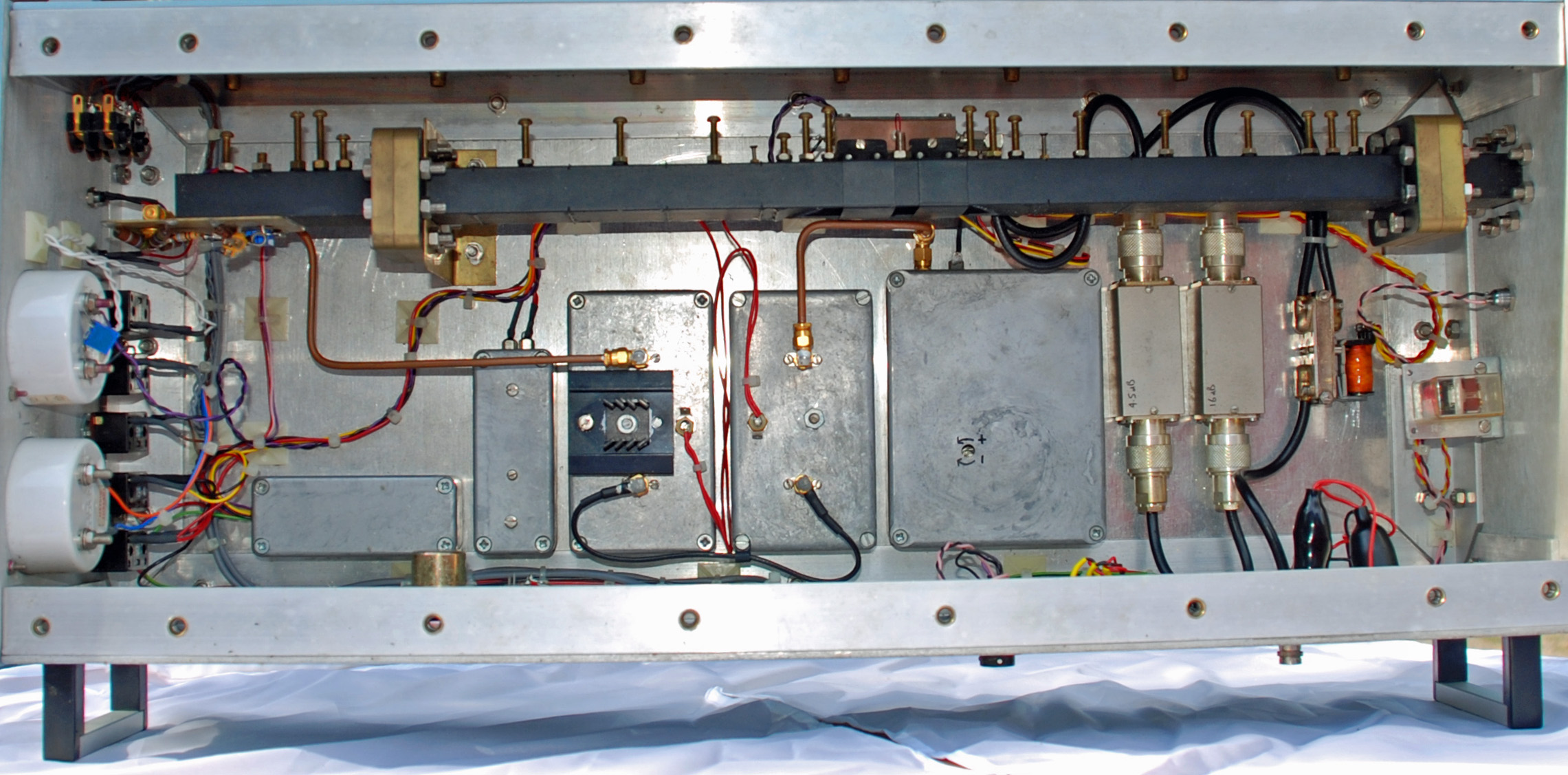
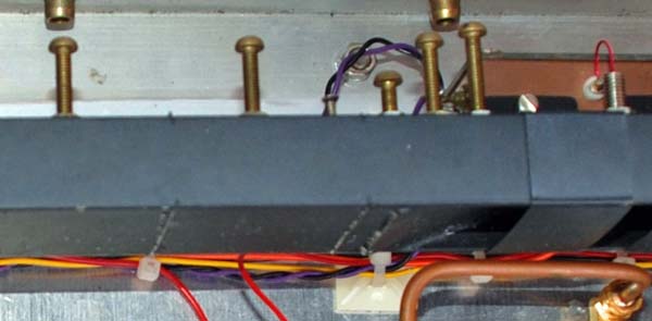
The JVL Transverter design is waveguide based and consists of LO filter, Mixer and Signal filter. The waveguide can be seen at the top of the picture below and its length defines the length of the whole apparatus.
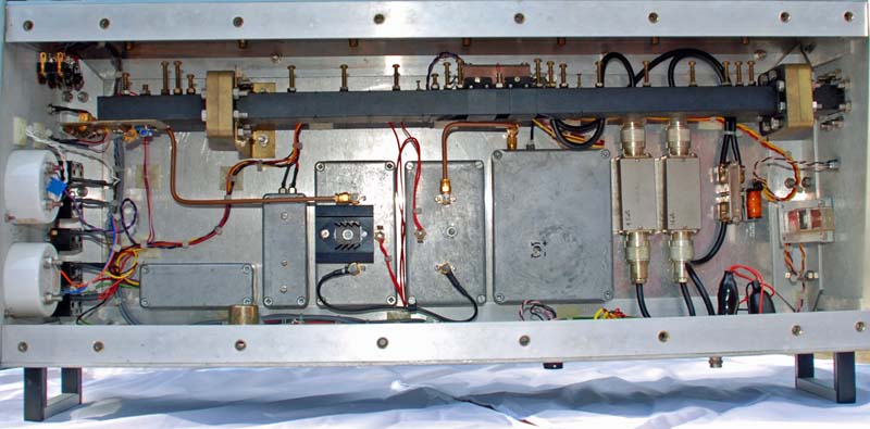
The build uses the classic box in box technique for maximum stability.

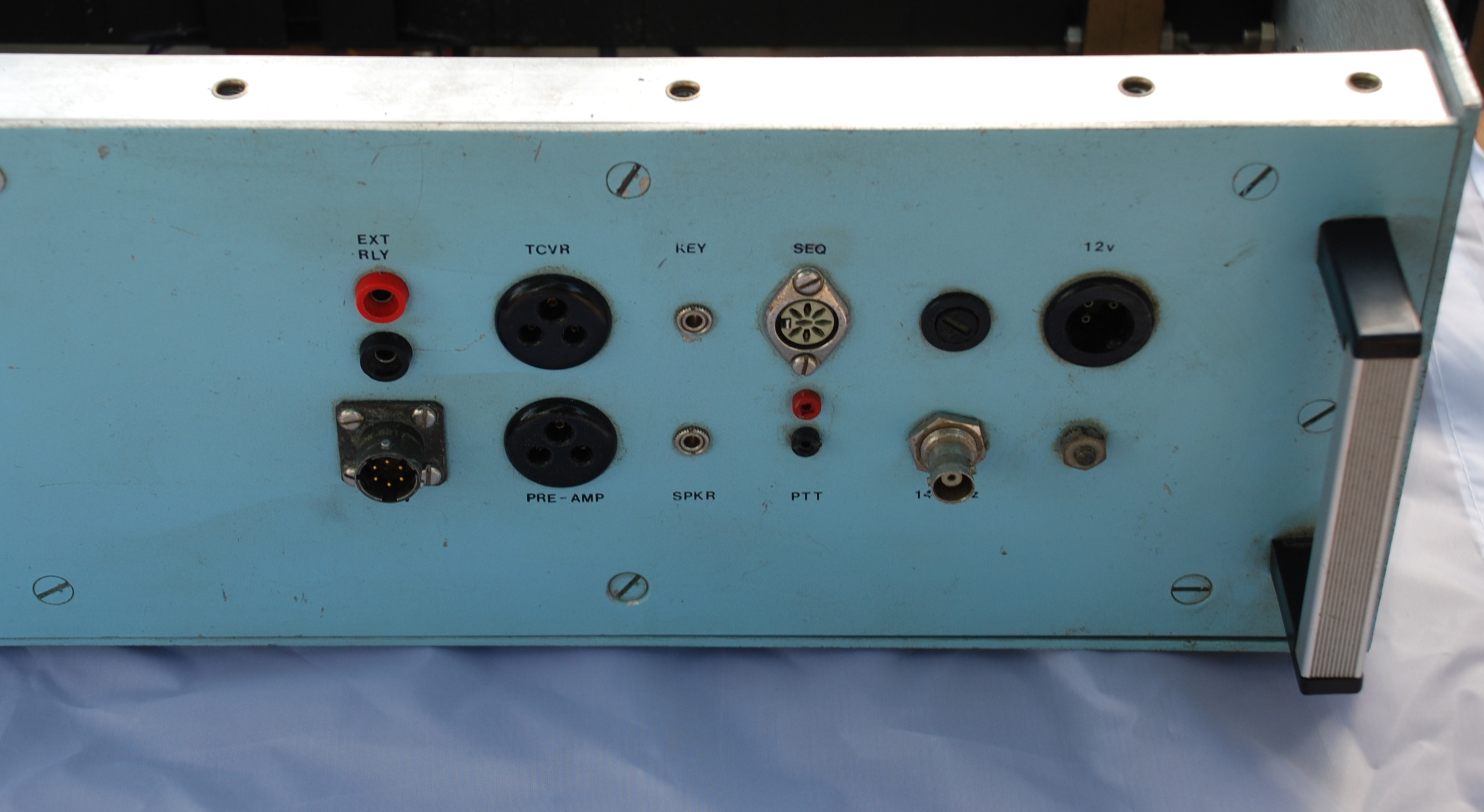
Connections are all brought to a single panel at the side of the transverter.
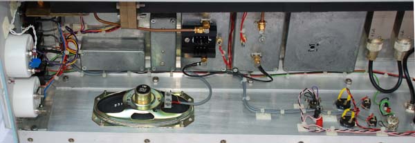
Also mounted on the same side as the connection patch is the loud speaker.
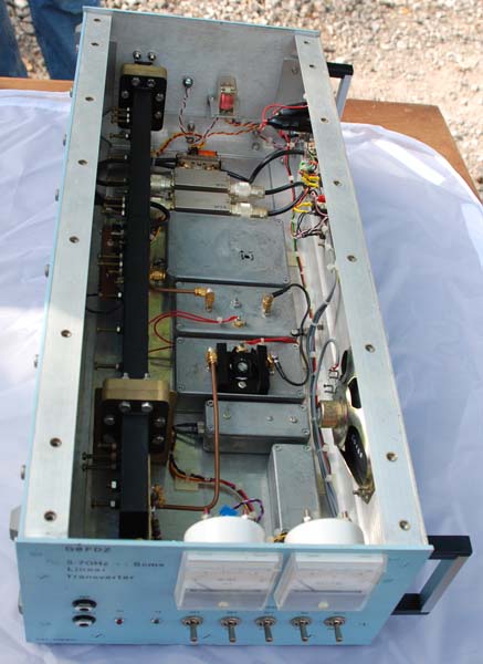
The transverter seen as full length.
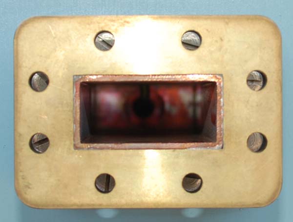
Looking into the waveguide. The final filter iris plate is at the far end. A matching screw can be seen entering the top face of the waveguide along the central axis of the broad face.
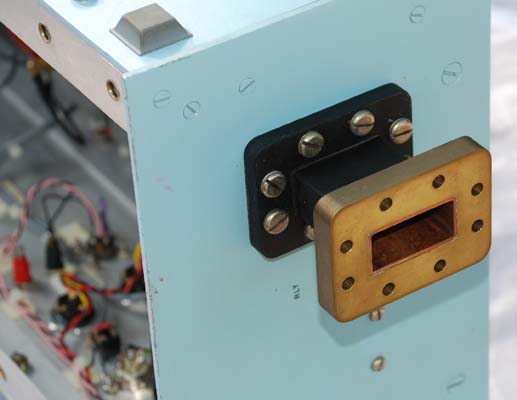
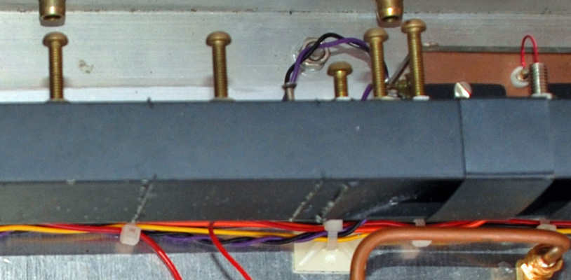
Waveguide for 6 cm is substantial and the fixings and flange make this clear.
Seen in close-up the method of letting the iris plates into the waveguide is revealed. The slots are cut in both broad faces as narrow as possible to just accept the iris plate. Once assembled the guide is heated and the minimum amount of solder is used to fix them into place. As solder is lossy at microwave frequencies it is important to minimise the entry of solder inside the waveguide.
|