|
The Solfan in-line Doppler module
Introduction by G8LSD writing in 2007
For some time, in the late 1980s, discussions had been taking place at Round Tables about the next generation of 10 GHz equipment. Our colleagues on the continent had generally moved ahead of us with GasFET narrowband systems. The feeling was that their economies were performing better than ours and we were being left behind. The choices seemed to be: Improve wideband, move to narrowband FM with varactor multipliers, build waveguide multimode narrowband gear with the excellent 1979 G3JVL design (approx 1 mW) or go commercial (100 mW)! The latter was how some amateurs regarded the purchase of the German SSB Electronics modules. These modules had to be built-up into a working system and could be regarded as components. After all the same orthodox amateurs thought nothing of using a commercial TWT to boost their signal.
At the VHF convention in Spring 1987 the microwave community saw the small tin plate boxes of the SSB Electronics modules for the first time. Little was said publicly at the time in favour of them but significantly more than a handful of amateurs placed orders at the show. These were then delivered in late summer - too late for 1987 operation. However, by the start of the 1988 season low voltage portable 10 GHz narrowband SSB had arrived.
The effects of this revolution were numerous: the UK amateur caught-up with Europe, the north-south divide closed once and for all, the north and south could have QSOs and a whole new dimension to 10 GHz experimentation commenced, more JVL transverters were built and used especially with TWT amplifiers as home stations, a ready reckoner of bearings as sheets of paper gave way to computers in the station and most sad of all a significant number of amateurs just disappeared off the band.
With hindsight Mike's rallying cry looks more like a recruiting sargeant for the new order. With so much work to do to improve wideband - why not just move into the new world.
Here is Mike's excellent critique of the options facing UK 10 GHz wideband activity at the end of 1988.
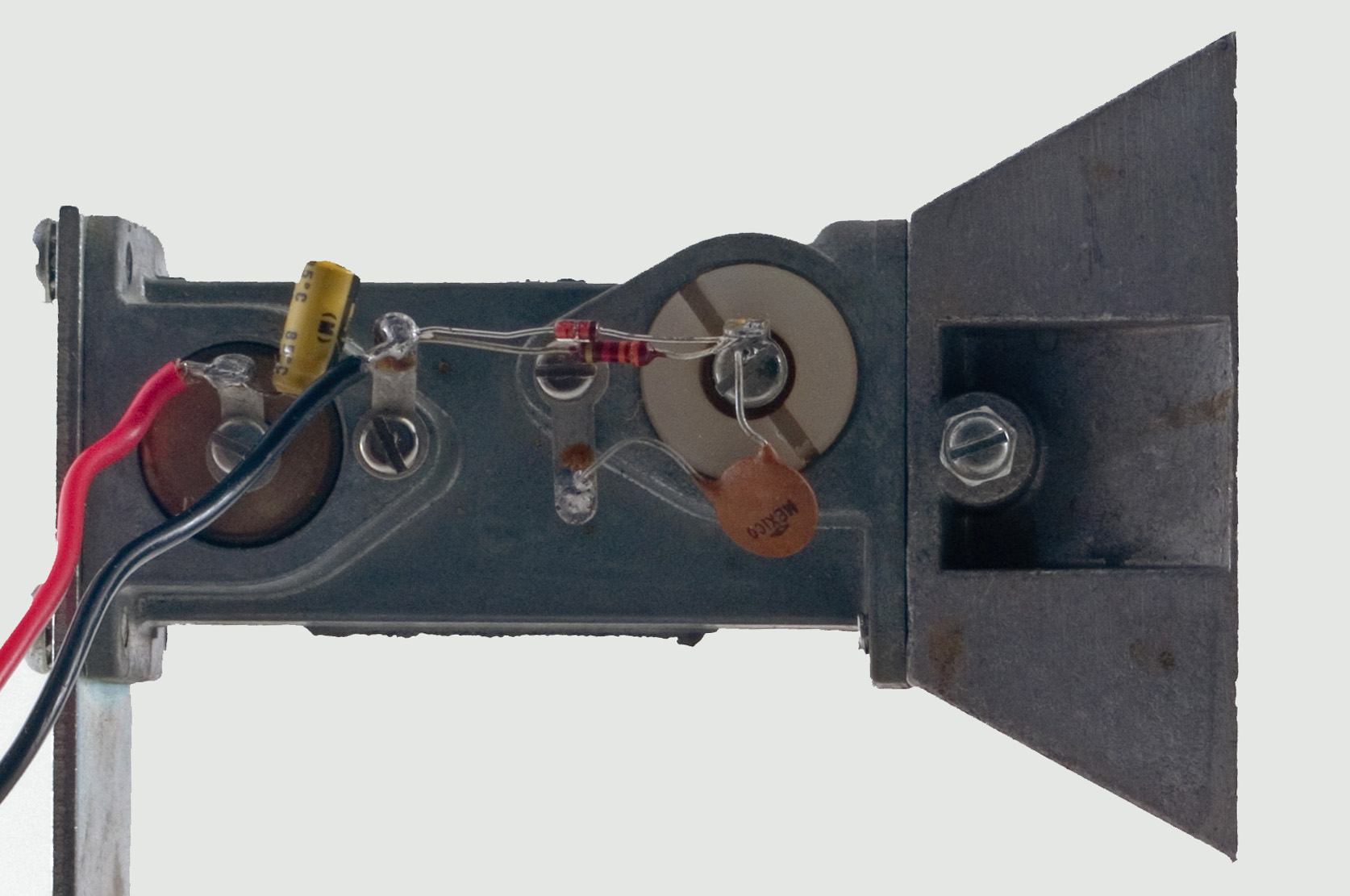
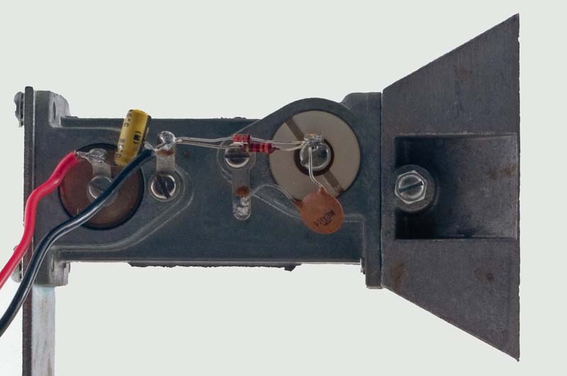
What is typical beginner's gear? The story probably reads something like this: 18 inch dish, Penny feed, Solfan in-line Gunn oscillator/mixer, 10.7 MHz IF fitted with a 200 to 250kHz-wide ceramic filter and a 7805 regulator/modulator. Pretty 'bog-standard' stuff so far -so what is wrong with it?
Well, the usual basic Gunn system will generally weigh in, when measured on professional test-gear (at Round Tables) with an open-ended waveguide sensitivity of somewhere around -95 to -105dBm. Quite adequate for working line-of-sight paths (even long ones), but inadequate for long line-of-sight paths under subnormal propagation conditions, or marginal or obstructed shorter paths. So what determines the measured sensitivity and what can be done to improve it?
In a Gunn-based rig, performance is dependant on several factors, many of which are related to the way in which the Gunn oscillator itself is designed, set up and used. In-line oscillator/mixers are an easy and convenient compromise and they make good receivers when set up correctly. Unfortunately, when adjusted for optimum mixer current (typically 0.25 to 1 mA), this means that only one to two milliwatts is available as the transmit output. A separate Gunn transmitter at 20 mW output is 10 to 13 dB better than the in-line device and it also means that you do not have to retune between transmit and receive, although you will have to acquire or devise some form of T/R switch and provide two Gunn supplies.
In my experience, the widely used Solfan in-line module usually suffers from far too much mixer drive - anywhere in the range two to five or more milli-Amps. This degrades receiver performance but improves transmit performance!
Adjusting the mixer current down to the more usual range by means of the screw immediately outside the oscillator cavity (just in front of the iris) is usually worth at least 3 dB on receive.
Often the mixer diode may be 'under par', possibly due to static damage during handling. So consider replacing the mixer device with a known good one before trying to optimise - this could also be worth a few extra receive dB.
Next let's consider some of the other usually non-optimised features of the basic system. Starting at the antenna and working backwards the most important of these, not necessarily in the most logical order, are:
- Maximise antenna gain by using the largest practicable dish, remembering that large dishes, are unmanageable for portable use -too large and heavy to carry and too narrow a beam-width, to point and maintain accurately. 39 inch (1m) is probably about maximum.
- Maximise antenna gain by using the largest practicable dish, remembering that large dishes, are unmanageable for portable use - too large and heavy to carry and too narrow a beam-width, to point and maintain accurately. 39 inch (1m) is probably about maximum.<=text=>
- Check your dish profile to make sure it is really a parabola: some readily available dishes are spherical rather than paraboloidal and thus suffer from significant loss of gain by having an indefinite focal point.
- Choose the TYPE of feed according to the f/D ratio of the dish. Proper dish illumination can be worth several dB. See The VHF/UHF Manual for, details of what feed is suitable for what type of dish. One thing is for sure, the Penny feed, as usually constructed, is none too clever with dishes of f/D less than about 0.33 to 0.35.
- A properly adjusted (focus and match) feed can also be worth several extra dB.
- Use of an RF preamplifier (if available) will be worth many dB, depending on input and output match and the following mixer match and performance.
- An optimised mixer, using a known good device and correct mixer drive, has already been mentioned.
- Image rejection at signal frequency is worth 3 dB, but is not usually practicable with an in-line device used as an unswitched transceiver.
- Install a good, low-noise IF head preamp as close as possible to the mixer to minimise the mixer to receiver coupling loss.
- Cutting receiver IF bandwidth from 250 kHz to 25 kHz is worth 10 dB, but needs a very stable oscillator.
- For optimum receive oscillator stability, use a front cavity iris-coupled oscillator and the highest power Gunn diode you can. The smallest iris hole needed to get the correct injection will ensure maximum stability and at the same time minimise signal loss into the oscillator. In this respect, a home-made oscillator which uses a replaceable iris plate is easier to optimise than the Solfan with its fixed-size iris.
- Effective AFC can improve Gunn stability performance to the point where worthwhile bandwidth reduction is realistic, with the advantages already outlined. 50 kHz should be quite realistic, with 25 kHz a distinct possibility.
- Gunn performance in terms of stability and noise can be profoundly affected by the 'quality' of the regulator/modulator circuit. Lack of screening, spurious noise and instability can all cause unwanted frequency modulation.
- Optimising the Gunn operating bias voltage to yield the lowest oscillator noise may gain several receive dB, especially when using a low-order IF the FM noise sidebands of a Gunn oscillator will usually extend for at least 15 MHz either side of the nominal frequency. Thus the common use of a 10.7MHz IF may be quite detrimental to overall performance. An IF of 30 MHz would be better in this respect.
- Optimising the Gunn operating bias voltage to yield the lowest oscillator noise may gain several receive dB, especially when using a low-order IF the FM noise sidebands of a Gunn oscillator will usually extend for at least 15 MHz either side of the nominal frequency. Thus the common use of a 10.7MHz IF may be quite detrimental to overall performance. An IF of 30 MHz would be better in this respect.
- Also in connection with the Gunn bias, electronic tuning by voltage pushing is often taken too far, ie, a voltage swing of several volts to maximise the tuning range without resort to mechanical (screw) tuning. Ideally, once the optimum voltage for least noise has been established, it should be preset and the fine-tuning voltage restricted to perhaps no more than -0.5 to + 0.5 V around this point. The Gunn will usually be least noisy when it is run at about 1 to 1.5V above the turn-on voltage. This is certainly not coincident with maximum power output and most beginners will, naturally, tend to set up their oscillators for maximum output rather than best performance. Ignore the temptation!
- If wide range voltage pushing is attempted, it is a good idea to systematically check the Gunn frequency with a wavemeter while slowly increasing the Gunn bias voltage. Most Gunn diodes operated at higher voltages to obtain maximum power output and voltage pushing will tend to jump modes and frequency, or even tune backwards for a short distance. This phenomenon can explain why paths which should work sometimes don't: the Gunn may have skipped over the frequency of interest, quite unintentionally!
Once all these improvements have been considered or carried out, then you can start to think about the other alternatives!
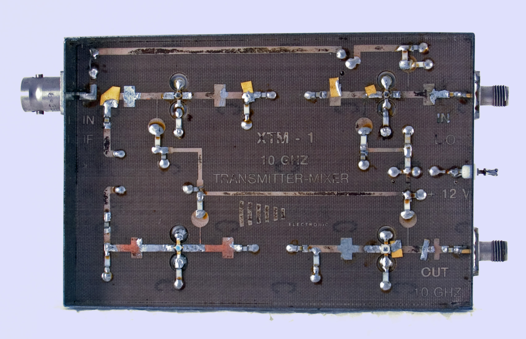
The SSB Electronics 10 GHz transmit mixer with 160 mW output, surface-mount component side.
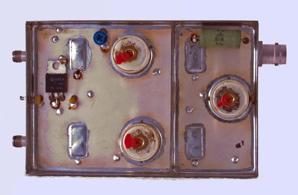
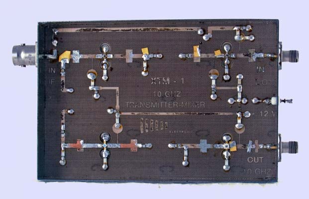
The groundplane side of the XTM-1, note the pill-box filters and 144 MHz terminating load.
|